


SOLAR ORBITER. Instrument boom


The Solar Orbiter deployable boom function is to support and deploy four instruments which, due to their sensitivity to magnetic fields, need to be placed far from the electromagnetic disturbances generated by the satellite.
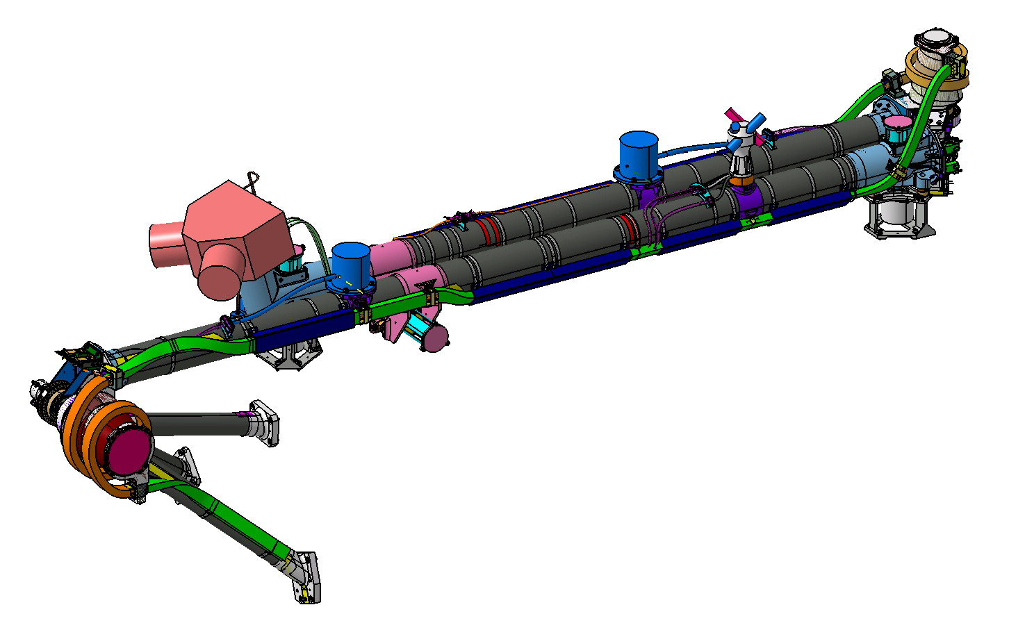
It consists of three rigid sections joined by two deployment mechanisms. Each section consists of titanium pieces affixed to CFRP pipes. During launch, the boom remains undeployed and secured to the satellite’s panels by means of a tripod and two hold-down mechanisms, while a third hold-down mechanism keeps the two deployable sections joined together.
The Solar Orbiter deployable boom function is to support and deploy four instruments which, due to their sensitivity to magnetic fields, need to be placed far from the electromagnetic disturbances generated by the satellite.
It consists of three rigid sections joined by two deployment mechanisms. Each section consists of titanium pieces affixed to CFRP pipes. During launch, the boom remains undeployed and secured to the satellite’s panels by means of a tripod and two hold-down mechanisms, while a third hold-down mechanism keeps the two deployable sections joined together. Once in orbit, deployment takes place in two sequences. Initially the two hold-down mechanisms are released and both sections are rotated 195° by the internal deployment mechanism until a stop point is reached, which defines the deployed position. The intermediate moving mechanism is then released and the external section rotates 180° with regard to the internal section by means of the external deployment mechanism, reaching the deployed position.
The deployment mechanisms consist of one hinge with spherical bearings and are clock spring-actuated. A viscous damper is included for smooth deployment. The mechanisms have a mechanical end-of-deployment stop point together with a hook-up system. They also include a potentiometer as a position sensor plus switches to monitor the final positions.
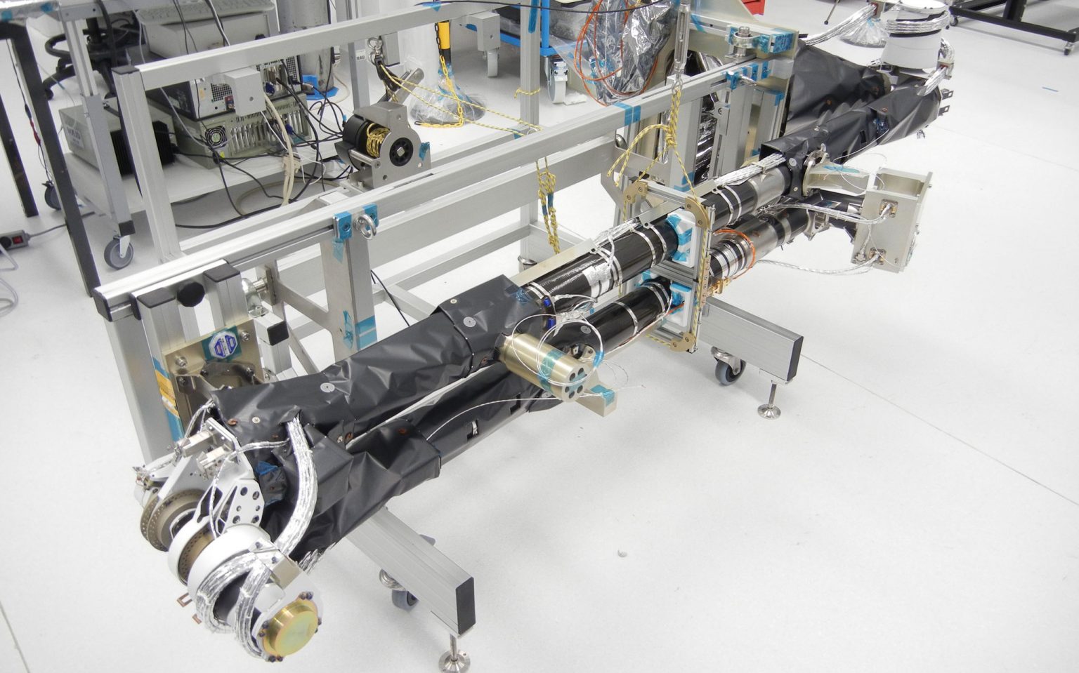
In order to adapt the subsystem to the thermal atmosphere, thermal control is included, which comprises both passive elements (thermal blankets and paint with suitable thermal-optical properties), and active elements (electric heaters and thermistors).
The subsystem includes the instrument cable bundles, the wiring required to transmit the signals from the position sensors and the thermistors, and the wiring to supply power to the electric heaters.
One important characteristic is the routing and fixing of the wiring along the pipes and around the deployment mechanisms.
Due to the strict magnetic cleanliness requirements, as far as possible, all the materials used are amagnetic (titanium, aluminium, CFRP, Vespel, beryllium copper, etc.), and in unavoidable cases of materials with a certain residual magnetism, exhaustive demagnetisation is performed.
- Characteristics:
- Undeployed length: 2250 mm
- Deployed length: 4400 mm
- Subsystem mass: 35 kg
- Instrument and wiring mass: 9.7 kg
- Stiffness – undeployed: 80 Hz
- Stiffness – deployed: 1.1 Hz
- Deployment angle – internal articulation: 195º
- Deployment angle – external articulation : 180º
- Deployment times – first section: < 90 s
- Deployment times – second section: < 90 s
- Vibration sine: 10 g
- Vibration random: 13 grms

