Entry open for sixth edition of the SENER Foundation Best Doctoral Thesis Award

Entry open for sixth edition of the SENER Foundation Best Doctoral Thesis Award

31/10/2017

The SENER Foundation has sent out the call for entrants to the sixth edition of the SENER Foundation Best Doctoral Thesis Award.

Entry is open to anyone who has obtained a doctorate from a university this calendar year 2017, in any of the following scientific and technological areas: Aerospace, Infrastructures and Transport, Power, Oil & Gas, or Marine. These awards seek to stimulate research at the very highest level, and the areas mentioned are the main technological and scientific areas in which SENER is active.

Candidates must send their entry in PDF format to the SENER Foundation (address: C/Severo Ochoa 4 (PTM) Tres Cantos – 28760 Madrid, Spain), and have until 1.00 pm on December 22, 2017 to do so.

As in previous editions, the SENER Foundation shall bestow a single award with prize money of €12,000 for the author of the winning thesis and another €3,000 for the supervisor(s) of the study (if there is more than one supervisor, this prize money is shared). The panel of judges’ decision will be published during the first quarter of 2018 and the prize will be presented in April that year.

The panel of judges will comprise supervisors of winning theses from previous editions (provided they are not connected to entries in the present edition), two doctors from SENER’s technical corps with experience in research work, doctorate-holding trustees of the SENER Foundation, and the Director and Secretary of the Foundation.

Assessment criteria will include, first of all, the research’s relevance and potential for application in the aforementioned scientific and technological areas; secondly, the quality of the thesis, and its impact in scientific dissemination channels (journals, patents, etc.), prizes or other accolades; and finally, clarity of presentation.

The full rules for the Best Doctoral Thesis Award are available on the SENER Foundation’s website.
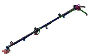
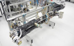
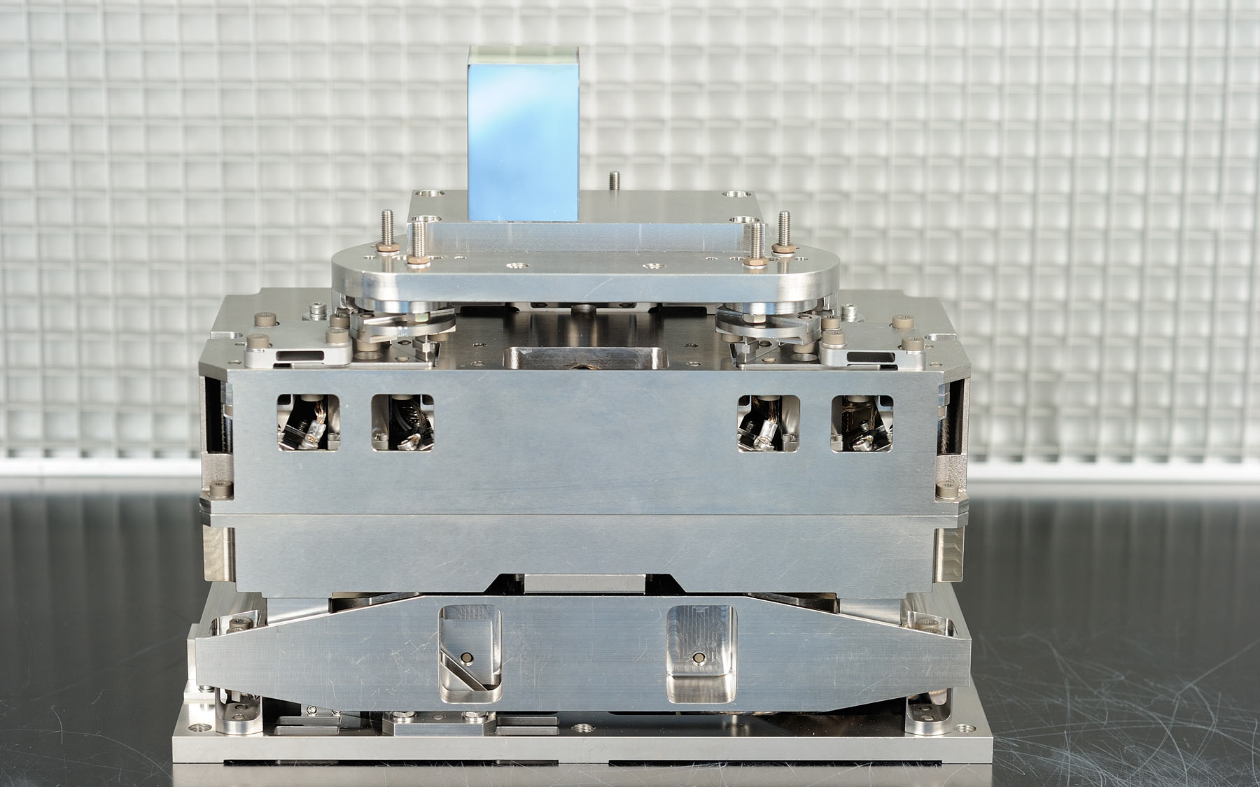
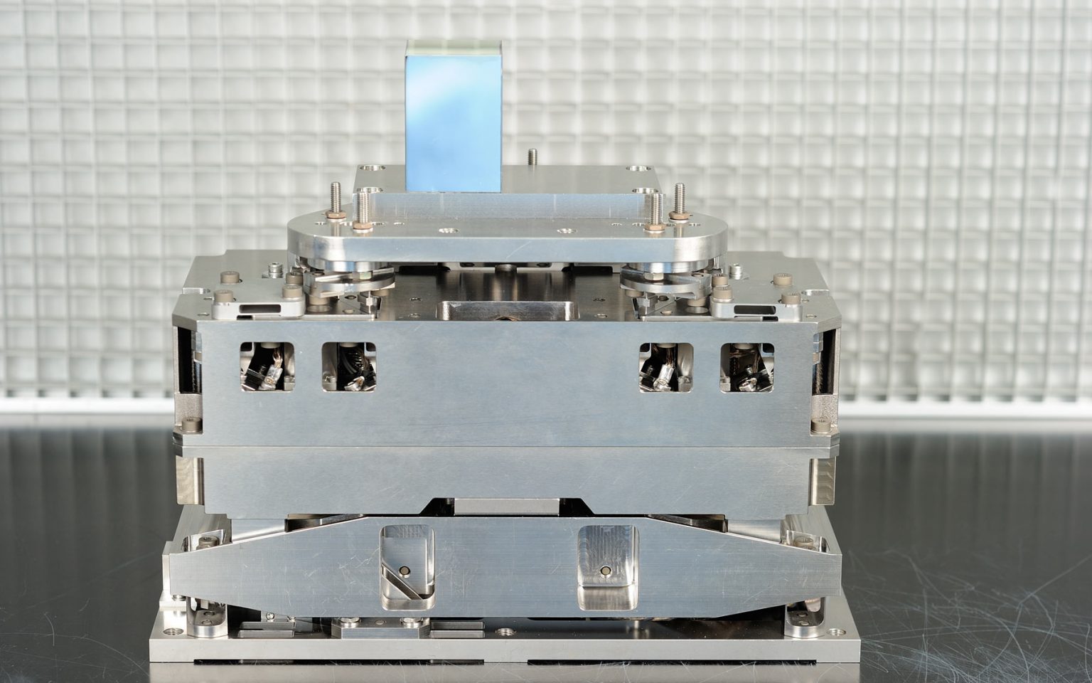
PDF

Press Release

Format: PDF

73,85 KB

On-line Ammonium Analyzer (OLAA)

On-line Ammonium Analyzer (OLAA)

1 2
Sener Space / Science & Earth observation / International
On-line Ammonium Analyzer (OLAA)
Client: ESA
Country: International

The On-line Ammonium Analyser (OLAA) emerged from ESA’s need to have an on-line system for monitoring ammonium in the ISS in order to verify that the various water recycling processes meet the quality requirements imposed by ESA.

To this end, the goal of the OLAA project is to determine, following a feasibility study to apply in space the various techniques used on Earth, the ideal analysis technique for the on-line measurement of ammonia in the water recycled in the ISS.

The project was led by Sener Aeroespacial,

Read more

The On-line Ammonium Analyser (OLAA) emerged from ESA’s need to have an on-line system for monitoring ammonium in the ISS in order to verify that the various water recycling processes meet the quality requirements imposed by ESA.

To this end, the goal of the OLAA project is to determine, following a feasibility study to apply in space the various techniques used on Earth, the ideal analysis technique for the on-line measurement of ammonia in the water recycled in the ISS.

The project was led by Sener Aeroespacial, which relied on contributions from the Autonomous University of Barcelona (UAB) and the University of Porto. Sener Aeroespacial was responsible for specifying the system requirements, for leading the phase to identify/select the techniques for measuring the ammonia, and for the space feasibility study, as well as for carrying out the conceptual design of the flight equipment on the basis of the ammonia monitoring technique selected.

Specifications

  • During the study, demonstrators were developed using spectrophotometry and potentiometric methods to evaluate the viability of the analysis techniques for monitoring ammonium.
  • The best results were obtained using the potentiometric method. This analysis technique was shown able to quantify ammonium in water in a concentration range of 0.1-100mg/L, to within an accuracy of 10% and an average response time of six minutes.
  • Its feasibility in microgravity environments was validated on a parabolic flight with a rocket. Tests confirmed that the system worked correctly in zero gravity.
Read less

Contact us

Contact us to find out how we can help you.

Meteosat Third Generation (MTG)

08.30.2017 pdf

Meteosat Third Generation (MTG)

08.30.2017
Format: pdf

SENER is responsible for three important contracts for Meteosat Third Generation (MTG), a mission from the European Space Agency (ESA) that is primarily geared toward broadening the capabilities of the Meteostat Second Generation (MSG) program, aimed at global and regional weather forecasting, as well as atmospheric monitoring.

IBDM Hard Capture System

IBDM Hard Capture System

1 6
Sener Space / In Orbit Operations / Space
IBDM Hard Capture System
Client: QinetiQ / ESA
Country: Space

The International Berthing and Docking Mechanism (IBDM) is the European androgynous low impact docking system that is capable of docking and berthing large and small spacecraft.

Sener, as part of a European consortium, has developed the Hard Capture System of the IBDM. The function of the HCS is to create a rigid structural connection to allow for a pressurised passageway between the two spacecraft. It also includes connections for the transfer of electrical power, data and fluids such as fuel.

The IBDM has been designed to be compatible with the International Docking System Standard (IDSS) and hence compatible with the ISS International Docking Adapters (IDA) on the US side of the International Space Station (ISS).

Read more

The International Berthing and Docking Mechanism (IBDM) is the European androgynous low impact docking system that is capable of docking and berthing large and small spacecraft.

Sener, as part of a European consortium, has developed the Hard Capture System of the IBDM. The function of the HCS is to create a rigid structural connection to allow for a pressurised passageway between the two spacecraft. It also includes connections for the transfer of electrical power, data and fluids such as fuel.

The IBDM has been designed to be compatible with the International Docking System Standard (IDSS) and hence compatible with the ISS International Docking Adapters (IDA) on the US side of the International Space Station (ISS). The possibility of modifying the system to accommodate new docking standards has been taken into account during the project phase, so it has the required flexibility to allow the integration of the IBDM into different vehicles.

This extremely precise and complex system may become a standard for manned space missions in the future.

The main components of the HCS are:

  • HCS Tunnel Assembly, which provides the structural integrity and accommodates seals, alignment pins and sensors.
  • HCS Hooks, with 12 independently driven hook units to achieve the structural mating, seal compressions and interface preload. It also accommodates the Contingency Release Devices, based on pyrobolts.
  • Separation System (three separators), which generates the required axial thrust to push off the hoisting vehicle from the ISS once the hooks are opened.
  • Two Resource Transfer Umbilical, with connectors to transfer power and data.
  • MMOD Cover, a Micro Meteorite and Orbital Debris Cover.
  • Thermal Control, active and passive (Multi-layer Insulation over the MMOD)

Sener is responsible for design, implementation, integration and testing of Separators, Resource Transfer Umbilical, MMOD cover, and two types of sensors: Ready To Hook Sensor (RTH) and Undocking Complete Sensor (UCS).

One of its potential applications is in the successor of the International Space Station, the Gateway station, whose construction, with SENER Aeroespacial participation with five different contracts, is planned for 2025. Ultimately, Gateway will be embedded in space around the Moon and will serve as a strategic point for distant space expeditions, such as a manned flight to Mars. Part of it will be the I-HAB, a habitat for astronauts arriving from Earth, developed by ESA member companies. I-HAB is expected to be equipped with the HCS system developed by Sener.

Read less

Contact us

Contact us to find out how we can help you.

Poster of SENER Aeroespacial in Space

03.01.2017 pdf

Poster of SENER Aeroespacial in Space

03.01.2017
Format: pdf

SENER is responsible for three important contracts for Meteosat Third Generation (MTG), a mission from the European Space Agency (ESA) that is primarily geared toward broadening the capabilities of the Meteostat Second Generation (MSG) program, aimed at global and regional weather forecasting, as well as atmospheric monitoring.

Meteosat Third Generation

Space

Science & Earth observation

Meteosat Third Generation

Case of success

Related content

12.15.2016 Science & Earth observation / Spain
06.11.2017 Science & Earth observation / Spain
08.28.2016 Science & Earth observation / Spain

Related projects in Space

10.22.2025 Science & Earth observation / Space

Contact us

Contact us to find out how we can help you.

Euclid scientific space probe

Space

Science & Earth observation

Euclid scientific space probe

Case of success

Content related to this project

Contact us

Contact us to find out how we can help you with your projects.

Attitude and orbit control system (AOCS) for Euclid

Attitude and orbit control system (AOCS) for Euclid

1 2
Sener Space / Science & Earth observation / Space
Attitude and orbit control system (AOCS) for Euclid
Client: THALES Alenia Space
Country: Space

Sener is responsible for the AOCS subsystem, under the direct coordination of Thales Alenia Space Italy (TASI), principal contractor for the mission.

Sener is in charge of the entire subsystem, which includes the equipment, functions and SW that control its attitude (pointing) and orbital position. The AOCS’s sensors include:

  • Fine Guidance Sensor (FGS)
  • Inertial Measurement Unit (IMU)
  • Star Trackers (STR)
  • Coarse Rate Sensors (CRS) and Sun Sensors (SS)
  • Reaction Wheels (RWL)
  • Micro Propulsion Subsystem (MPS) and Reaction Control Subsystem (RCS)

Eight Sener subcontractors from different countries are participating in the subsystem (including subcontractors from the Netherlands,

Read more

Sener is responsible for the AOCS subsystem, under the direct coordination of Thales Alenia Space Italy (TASI), principal contractor for the mission.

Sener is in charge of the entire subsystem, which includes the equipment, functions and SW that control its attitude (pointing) and orbital position. The AOCS’s sensors include:

  • Fine Guidance Sensor (FGS)
  • Inertial Measurement Unit (IMU)
  • Star Trackers (STR)
  • Coarse Rate Sensors (CRS) and Sun Sensors (SS)
  • Reaction Wheels (RWL)
  • Micro Propulsion Subsystem (MPS) and Reaction Control Subsystem (RCS)

Eight Sener subcontractors from different countries are participating in the subsystem (including subcontractors from the Netherlands, France, Germany, Italy, Portugal, and the US), while the client itself is providing the FGS, MPS and RCS.

The operating logic includes multiple modes and functions which are implemented in the SW of the AOCS, while also integrated in the SW of the central computer. The functions of the AOCS include determining and controlling the satellite’s attitude in all the modes; orbital maneuvers; equipment management and control; fault management (FDIR); interactions with the central software; and management of the AOCS’s data, telemetry and telecommands.

The project includes the preliminary and detailed design, production, verification, classification, delivery, and in-orbit commissioning. The AOCS provides hitherto unseen levels of performance in terms of pointing and stability (75 milli-arcsec., 99.7% C.L.), which will also give the FGS, IMU, MPS, etc. the highest levels of performance. Furthermore, the RWL must compensate for any disturbances (including those caused by the actuation of the mechanisms), while also preventing the transmission of the characteristic (micro-)vibrations, meaning they require very special characteristics and operation.

The AOCS’s SW corresponding to its different modes will be generated using Model Based Design Tools, with subsequent automatic generation of code from these models for the first time on an ESA scientific mission.

Read less

Contact us

Contact us to find out how we can help you with your projects.

SOLAR ORBITER. Instrument boom

SOLAR ORBITER. Instrument boom

1 3
Sener Space / Science & Earth observation / International
SOLAR ORBITER. Instrument boom
Client: ADS UK / ESA
Country: International

The Solar Orbiter deployable boom function is to support and deploy four instruments which, due to their sensitivity to magnetic fields, need to be placed far from the electromagnetic disturbances generated by the satellite.

It consists of three rigid sections joined by two deployment mechanisms. Each section consists of titanium pieces affixed to CFRP pipes. During launch, the boom remains undeployed and secured to the satellite’s panels by means of a tripod and two hold-down mechanisms, while a third hold-down mechanism keeps the two deployable sections joined together.

Read more

The Solar Orbiter deployable boom function is to support and deploy four instruments which, due to their sensitivity to magnetic fields, need to be placed far from the electromagnetic disturbances generated by the satellite.

It consists of three rigid sections joined by two deployment mechanisms. Each section consists of titanium pieces affixed to CFRP pipes. During launch, the boom remains undeployed and secured to the satellite’s panels by means of a tripod and two hold-down mechanisms, while a third hold-down mechanism keeps the two deployable sections joined together. Once in orbit, deployment takes place in two sequences. Initially the two hold-down mechanisms are released and both sections are rotated 195° by the internal deployment mechanism until a stop point is reached, which defines the deployed position. The intermediate moving mechanism is then released and the external section rotates 180° with regard to the internal section by means of the external deployment mechanism, reaching the deployed position.

The deployment mechanisms consist of one hinge with spherical bearings and are clock spring-actuated. A viscous damper is included for smooth deployment. The mechanisms have a mechanical end-of-deployment stop point together with a hook-up system. They also include a potentiometer as a position sensor plus switches to monitor the final positions.

In order to adapt the subsystem to the thermal atmosphere, thermal control is included, which comprises both passive elements (thermal blankets and paint with suitable thermal-optical properties), and active elements (electric heaters and thermistors).

The subsystem includes the instrument cable bundles, the wiring required to transmit the signals from the position sensors and the thermistors, and the wiring to supply power to the electric heaters.

One important characteristic is the routing and fixing of the wiring along the pipes and around the deployment mechanisms.

Due to the strict magnetic cleanliness requirements, as far as possible, all the materials used are amagnetic (titanium, aluminium, CFRP, Vespel, beryllium copper, etc.), and in unavoidable cases of materials with a certain residual magnetism, exhaustive demagnetisation is performed.

  • Characteristics:
  • Undeployed length: 2250 mm
  • Deployed length: 4400 mm
  • Subsystem mass: 35 kg
  • Instrument and wiring mass: 9.7 kg
  • Stiffness – undeployed: 80 Hz
  • Stiffness – deployed: 1.1 Hz
  • Deployment angle – internal articulation: 195º
  • Deployment angle – external articulation : 180º
  • Deployment times – first section: < 90 s
  • Deployment times – second section: < 90 s
  • Vibration  sine: 10 g
  • Vibration random: 13 grms
Read less

Contact us

Contact us to find out how we can help you.

Secondary Mirror Refocusing Mechanism (M2M) of the Euclid telescope

Secondary Mirror Refocusing Mechanism (M2M) of the Euclid telescope

1 3
Sener Space / Science & Earth observation / Space
Secondary Mirror Refocusing Mechanism (M2M) of the Euclid telescope
Client: ADS F / TAS-I / ESA
Country: Space

At Sener, we develop the Secondary Mirror Refocusing Mechanism (M2M). The M2MM is a positioning mechanism with 5 degrees of freedom which allows the movement and adjustment of the secondary mirror (M2M) of the Euclid telescope to guarantee the optical quality required in orbit, necessary to recover telescope misalignment caused by the difference in conditions between the earth and space.

Characteristics:

  • Radiation environment: The unit is designed to tolerate a uniformly distributed total dose of 22 krad inside the box.
Read more

At Sener, we develop the Secondary Mirror Refocusing Mechanism (M2M). The M2MM is a positioning mechanism with 5 degrees of freedom which allows the movement and adjustment of the secondary mirror (M2M) of the Euclid telescope to guarantee the optical quality required in orbit, necessary to recover telescope misalignment caused by the difference in conditions between the earth and space.

Characteristics:

  • Radiation environment: The unit is designed to tolerate a uniformly distributed total dose of 22 krad inside the box.
  • Mass: MDE 2.1 kg. Harness 1.6Kg. Mechanism 4.45 kg
  • Thermal:
       – MDE operating range: 250K – 313K; non operating range: 230K – 313K.
    – M2MM operating range: 110K – 313K.
    – Harness operating range from 110K to 313K and support a gradient of 203K.
    – Special cabling to connect the mechanisms to the electronics with low thermal conductivity.
    – Max. dissipation by conduction for MDE < 8W .
    – Max. dissipation by radiation for MDE < 2W.
    – Harness transfer in cryogenic zone < 0.0005 W in non-operational mode
  • Functional: Mechanical Resolution is half micron resolution over a travel of +/- 225 µm with stable positions and high load capability to withstand launch loads without losing a given position in a compact volume.
    – Positioning method based on a stepper motor.
    – Adjustment in 3 degrees of freedom of translation.
    – Adjustment in 2 degrees of freedom of rotation.
    – Linear resolution <0.050 μm.
    – Angular resolution <5μrad.
    – Range of linear operation 300 μm.
    – Range of angular operation 2mrad.
    – Precision of 2 μm for linear adjustments.
    – Precision of 30 μrad for angular adjustments.
  • Redundancy: Two fully redundant sections in a single box.
  • Power:  Each section powered by a 10W isolation converter.
  • Control: Each section provided with an “intelligent” device capable of decoding all telecommands received via serial channels, (MIL-STD-1553, preferred) providing the switching sequences required by the motors, and encoding the status information to provide serial telemetry.
    Compact electronics for the operation and control of the twin mechanisms (up to 10 degrees of freedom).
  • Motors drive: Ten independently biphased motors (with main and redundant wiring) can be managed by MDE main and redundant section in cold redundancy.
Read less

Related content

Contact us

Contact us to find out how we can help you with your projects.