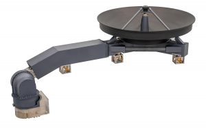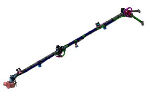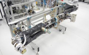


High gain Antenna Deployment and Pointing Mechanism of the Euclid probe
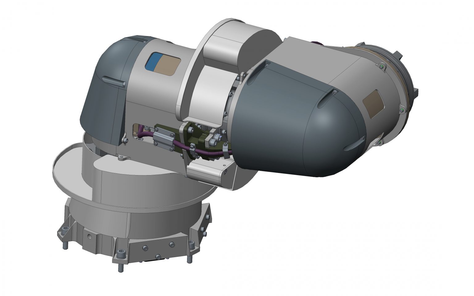


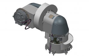
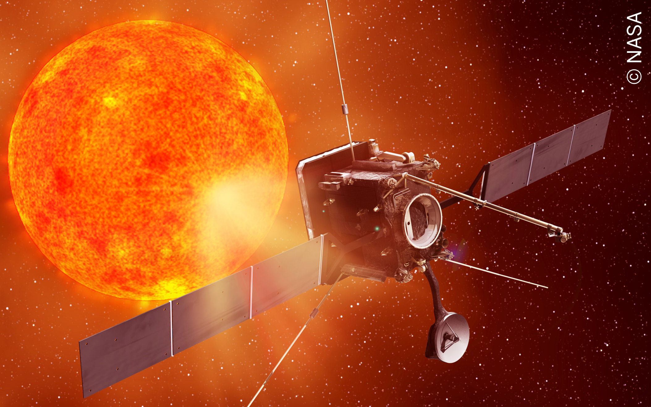
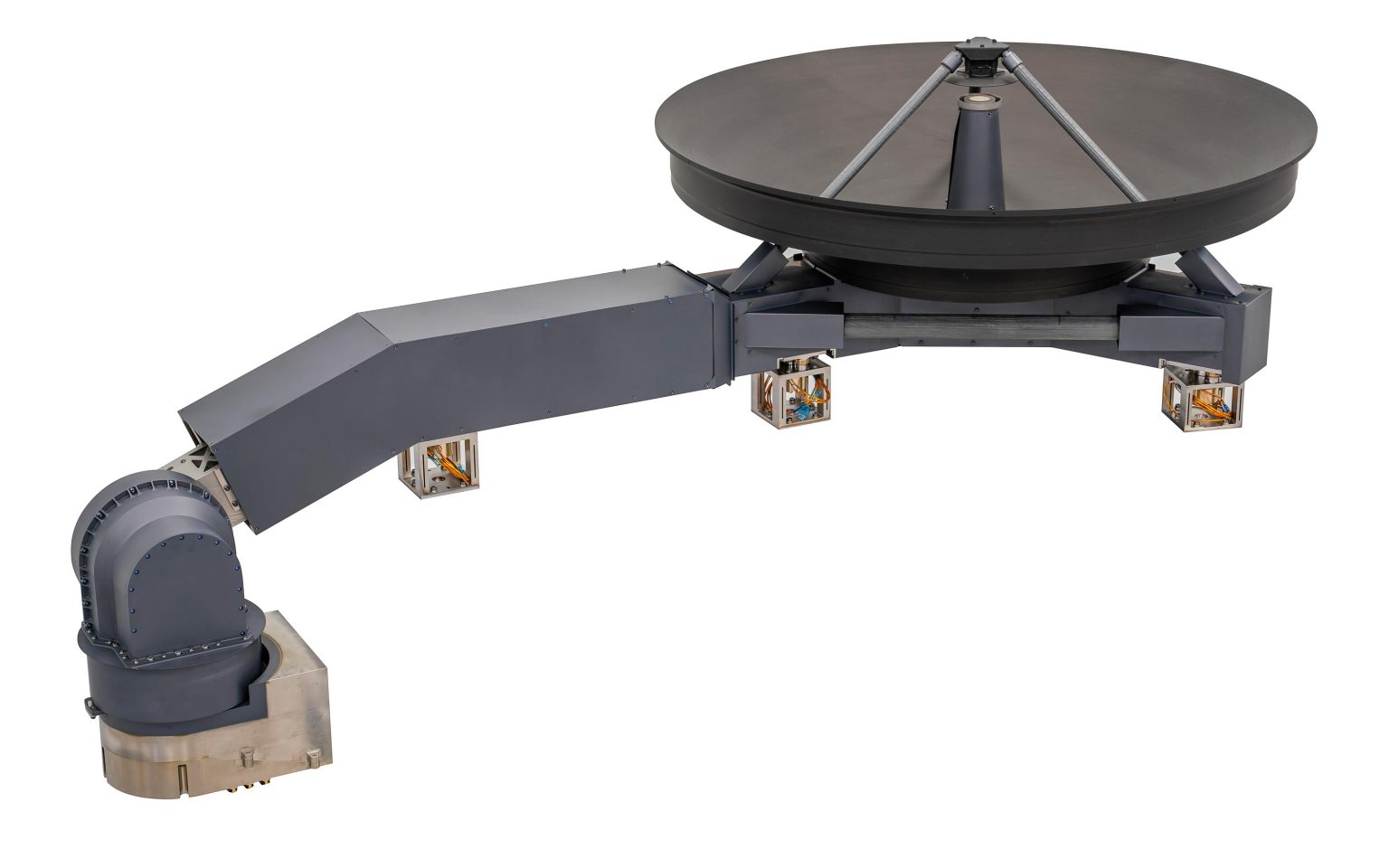
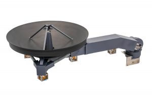
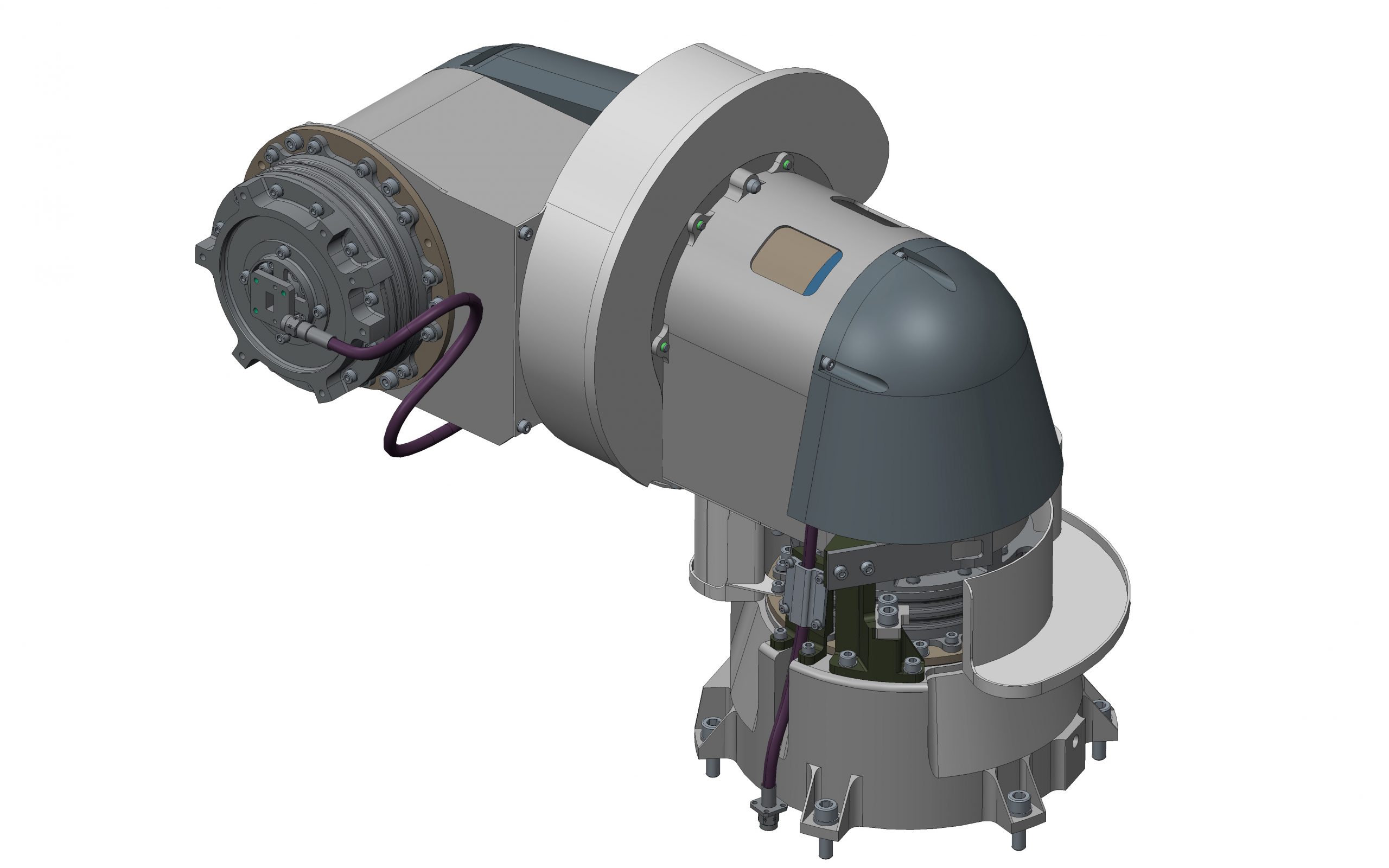
Sener is developing the high gain antenna deployment and pointing mechanism (HGA ADPM) for the Euclid scientific space probe. It is a precision assembly comprised of three axes, one for antenna deployment and the other two for pointing. The assembly transmits two radio-frequency signals from the satellite to the antennae. The signals are on the K band (between 25.5 and 27 GHz) for the high gain antenna, and on the X band (between 7.1 and 8.5 GHz) for the low gain antenna.
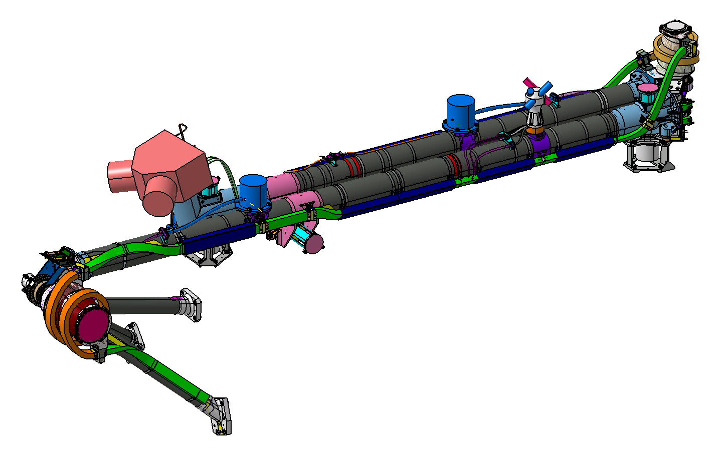
Main mechanism components:
- Actuators: The number of actuators and rotation axes are the same.
Sener is developing the high gain antenna deployment and pointing mechanism (HGA ADPM) for the Euclid scientific space probe. It is a precision assembly comprised of three axes, one for antenna deployment and the other two for pointing. The assembly transmits two radio-frequency signals from the satellite to the antennae. The signals are on the K band (between 25.5 and 27 GHz) for the high gain antenna, and on the X band (between 7.1 and 8.5 GHz) for the low gain antenna.
Main mechanism components:
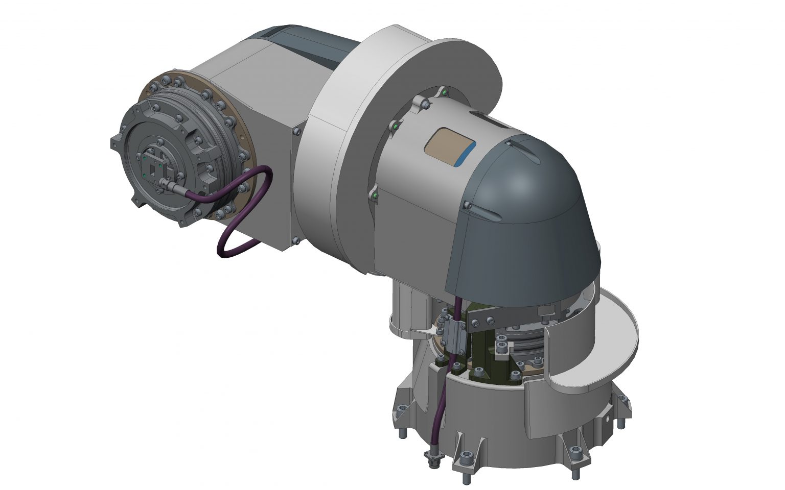
- Actuators: The number of actuators and rotation axes are the same. In this case there are three: for deployment, azimuth, and elevation. Each one of them comprises among others:
- Stepper motor
- Integrated bearing system
- Gear (harmonic)
- Positioning sensors (fine and coarse potentiometers for each Az. & El.))
- Machined parts
- Internal ball bearing
- K band rotary joint: a rigid joint used to transmit the radiofrequency single despite the assembly”s rotation. There is one on each actuator.
- X band cable: used to transmit the X band signal.
- Flexible cable: used to send the electric signals and power to the actuator, sensors, thermistors and thermal resistances.
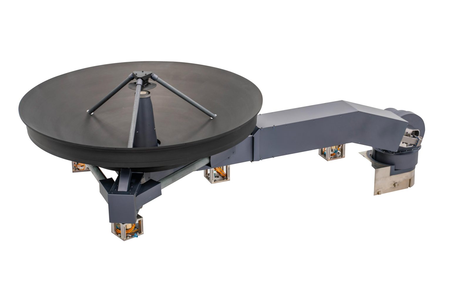
- L-structure: the structural element that joins the actuators.
- Support: the structural element that joins the deployment actuator to the interface with the satellite.
- The K band rotary joint and the actuator are specific Sener developments.
Characteristics:
- Mass: 10.5 kg.
- Power: 6.5 W per moving axis (steer).
- Pointing precision: ±0.005º in open loop.
- Speeds: 0.3º/s per axis.
- Radio frecuency (RF):
· Insertion Loss (K band/X band): < 1.2 dB / 1.5 dB
· Return Loss (K band/X band): > 18 dB / > 16.5 dB
· Radio-frequency power handling (K band/X band): min. 100 W/ min. 20 W
Related content
Contact us
Contact us to find out how we can help you with your projects.