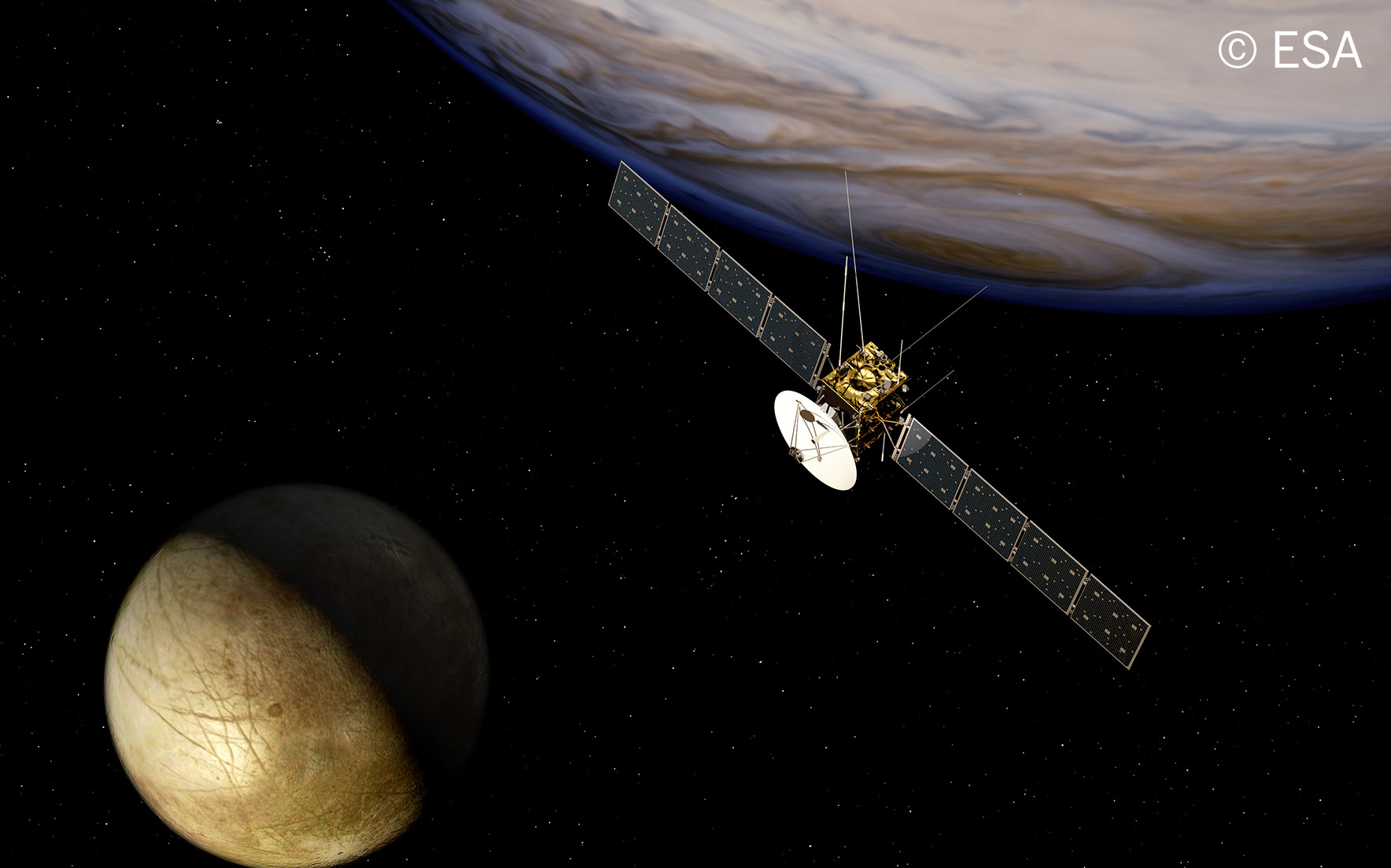
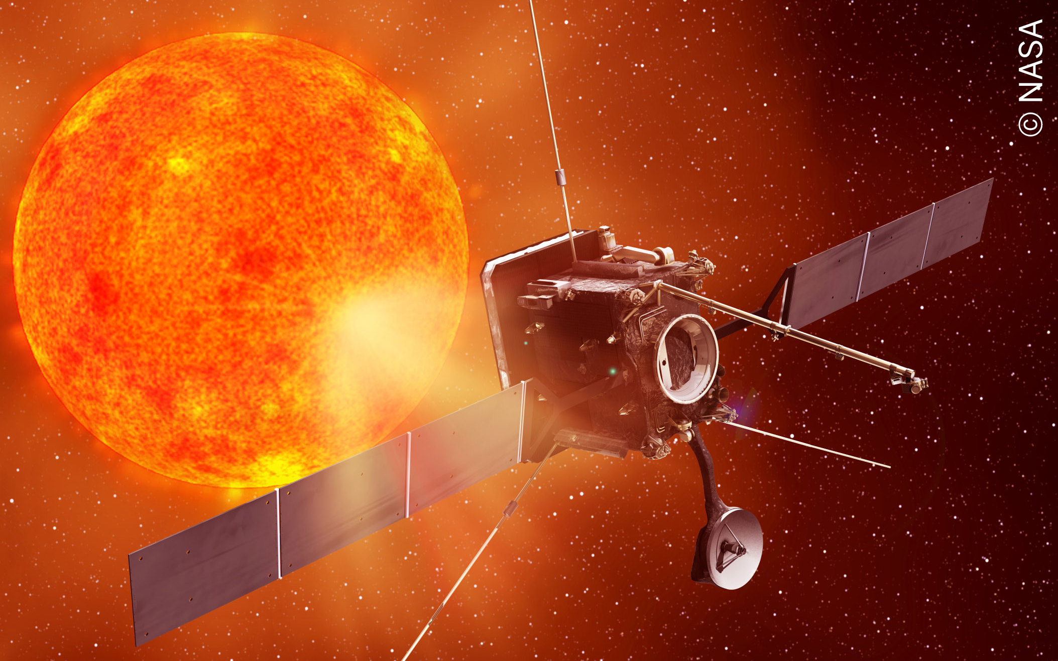
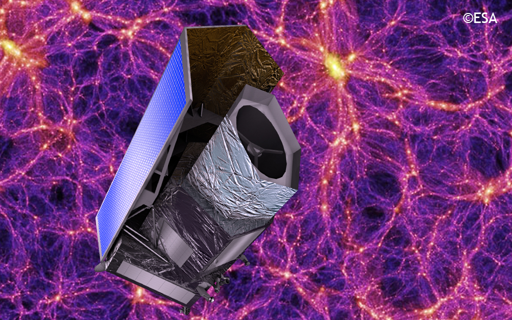
The Sunshield Drive Electronics (SDE) is an electrical unit designed to control a stepper motors per section (Main or Redundant) which shall actuate over the of the GAIA Deployable Sunshield Assembly (DSA) Structure.
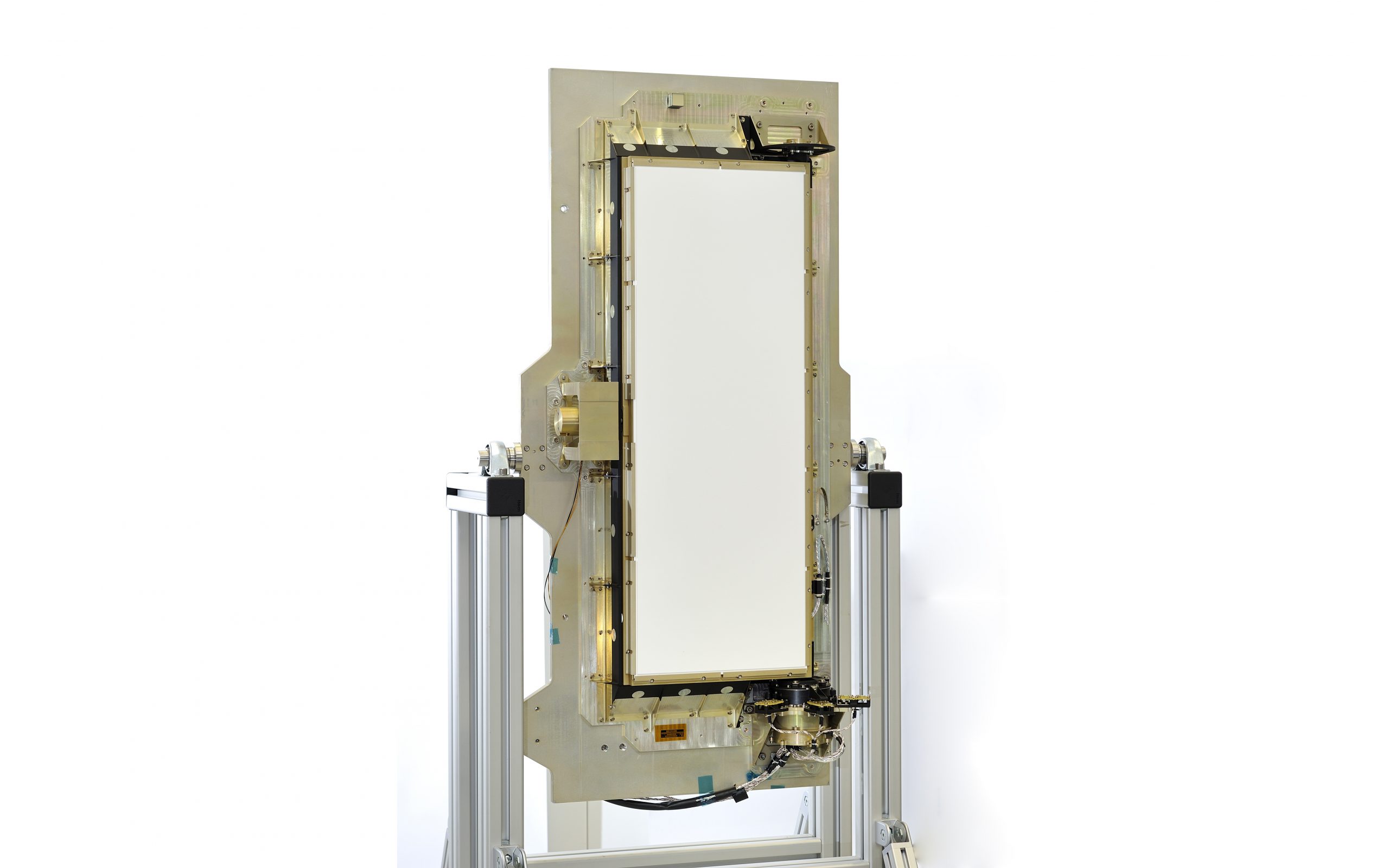
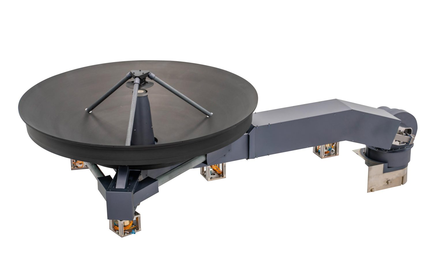
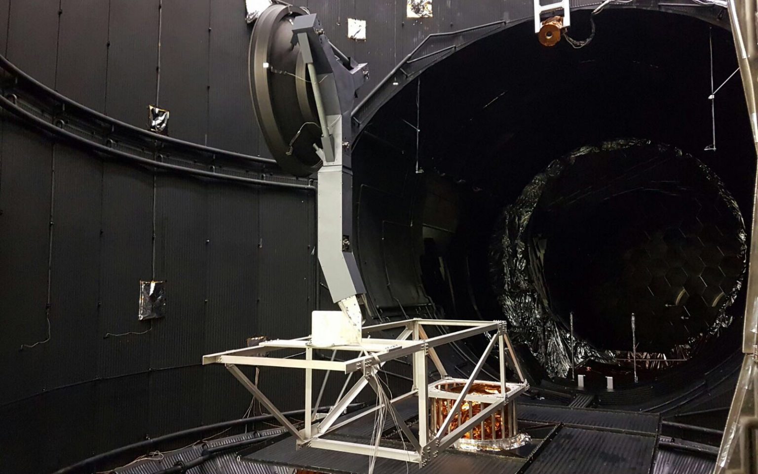
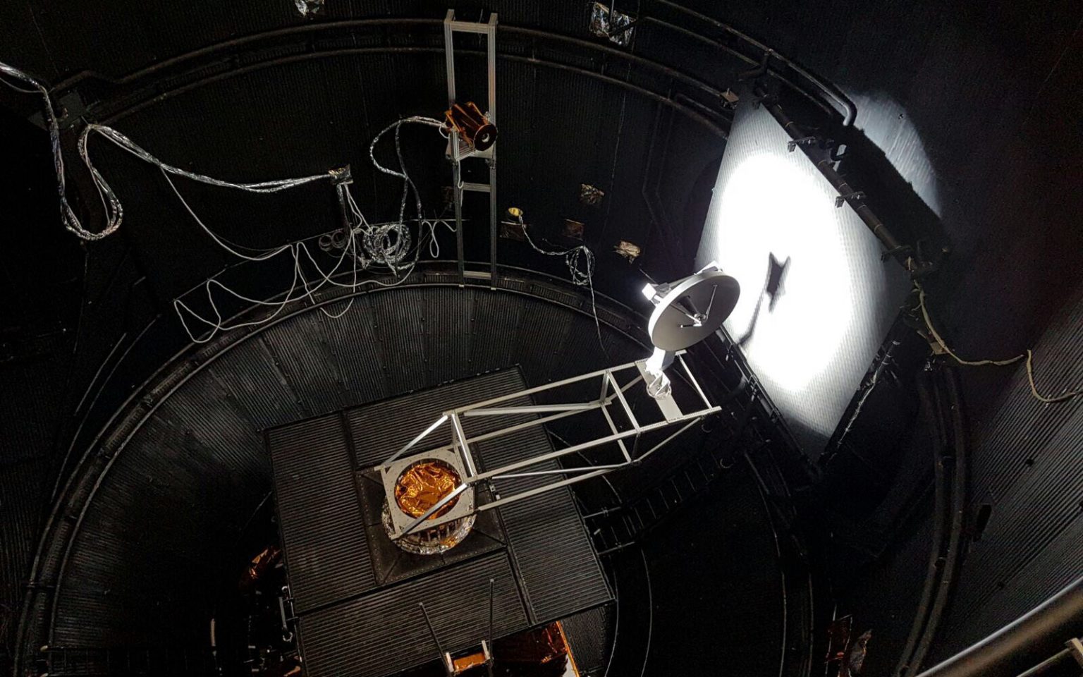
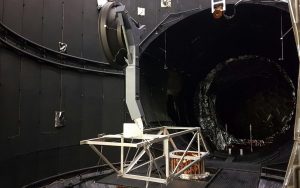
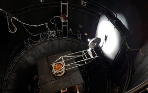
During the qualification campaign of the GAIA Deployable Sunshield Assembly (DSA) it was identified the need of implementation of an active motorisation device apart and in addition to the implemented deployment springs on each of the 12 section that forms the Sunshield. The deployment of the DSA is actuated by those springs mounted on each DSA section at the deployment.
The Sunshield Drive Electronics (SDE) is an electrical unit designed to control a stepper motors per section (Main or Redundant) which shall actuate over the of the GAIA Deployable Sunshield Assembly (DSA) Structure.
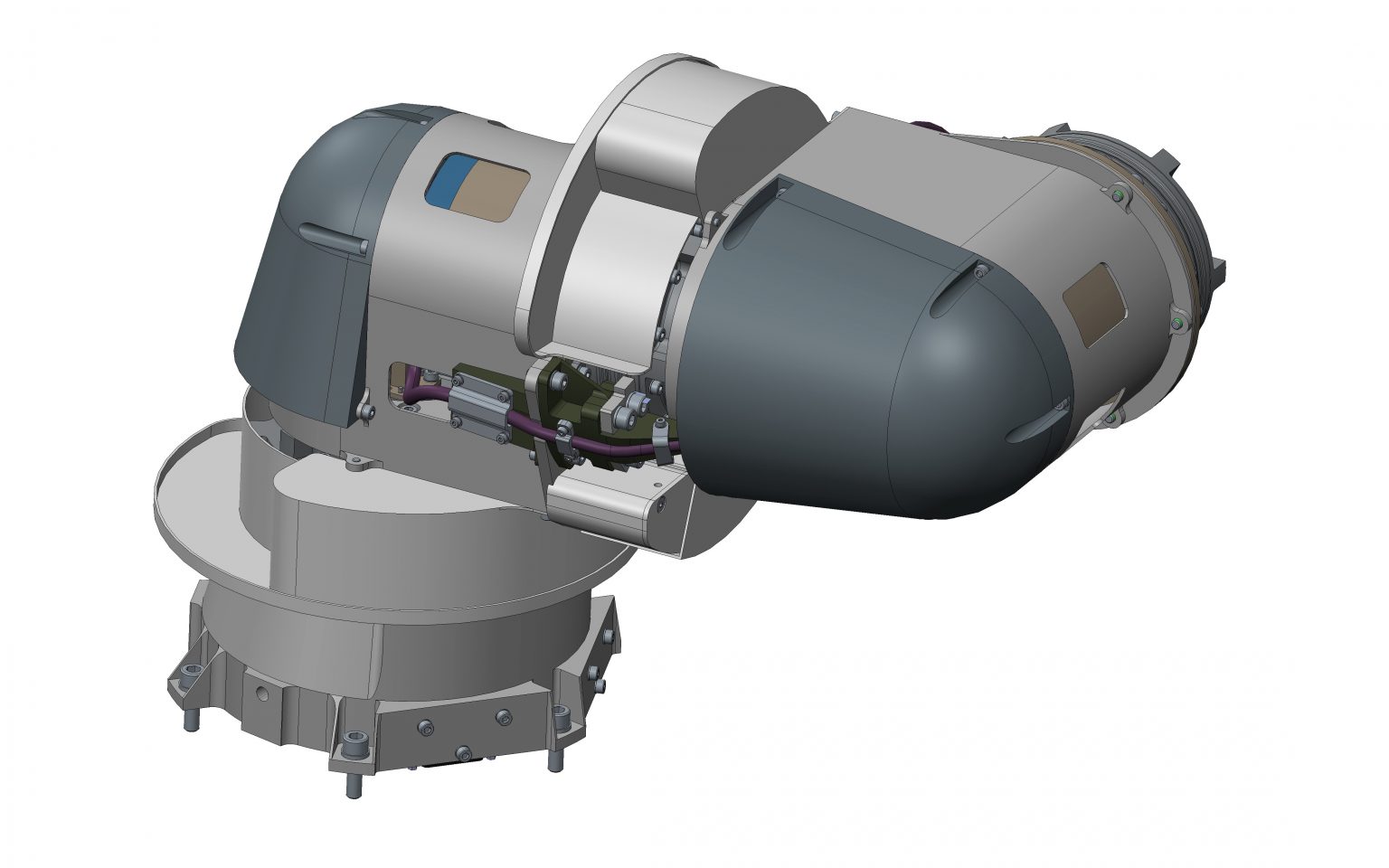
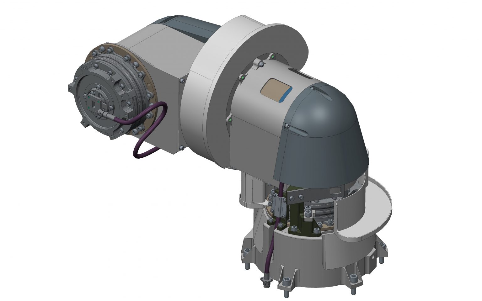
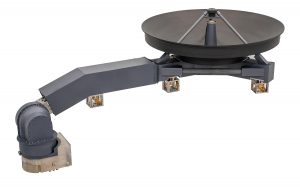
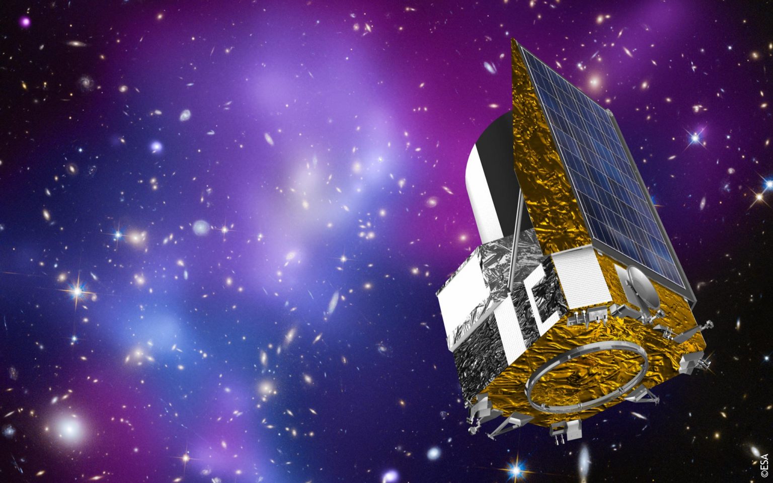
During the qualification campaign of the GAIA Deployable Sunshield Assembly (DSA) it was identified the need of implementation of an active motorisation device apart and in addition to the implemented deployment springs on each of the 12 section that forms the Sunshield. The deployment of the DSA is actuated by those springs mounted on each DSA section at the deployment. The implementation of two actuators linked to two opposite frames through a four bar linkage provides braking capability during a nominal deployment as well as additional motorisation in case resistances to the deployment increase. This improves the reliability ae level of the hinges and provides motorisation to overcome the resistance forces acting against thnd motorisation of the deployment.
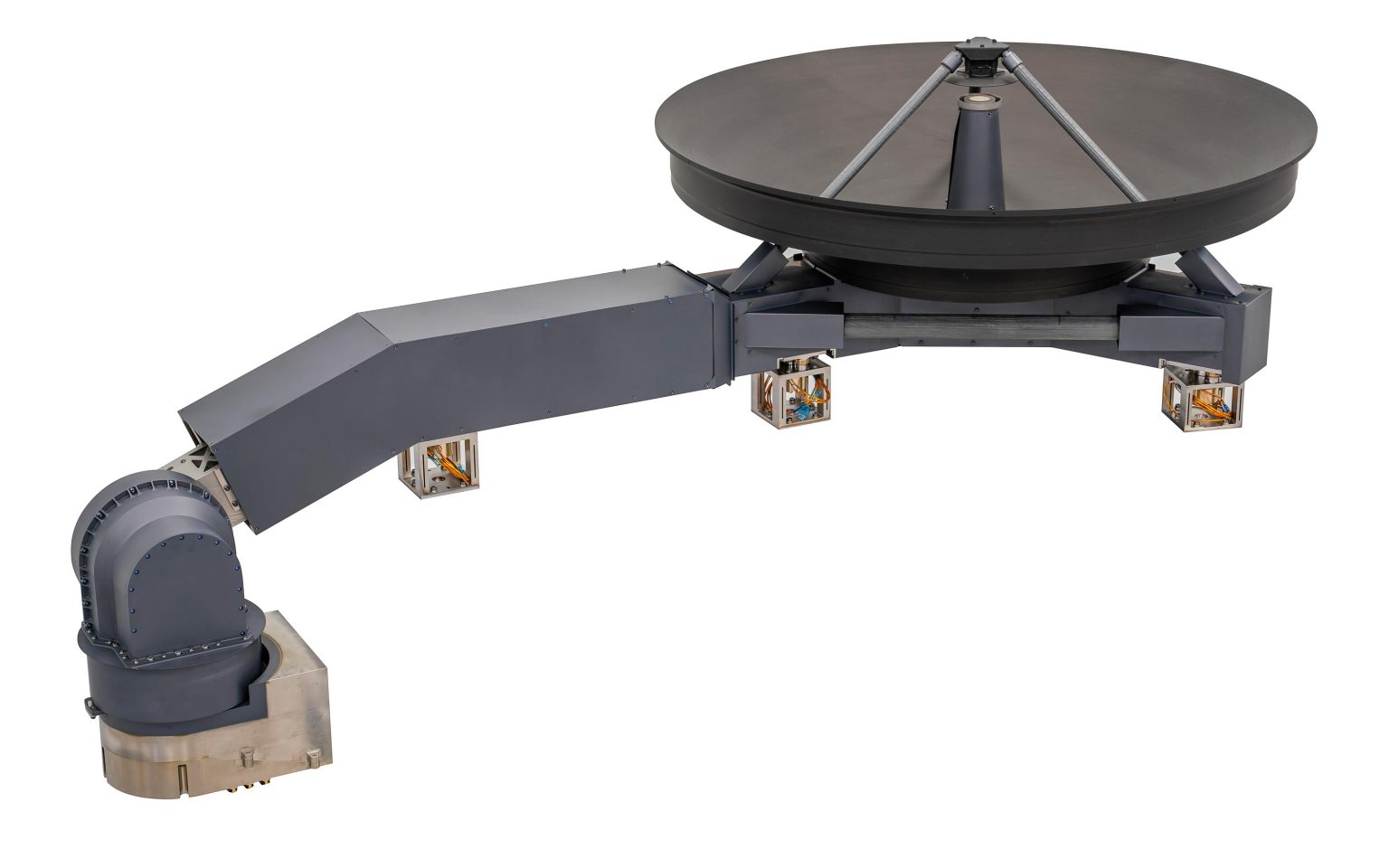
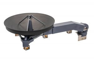
The DSA Drive Subsystem includes the following hardware :
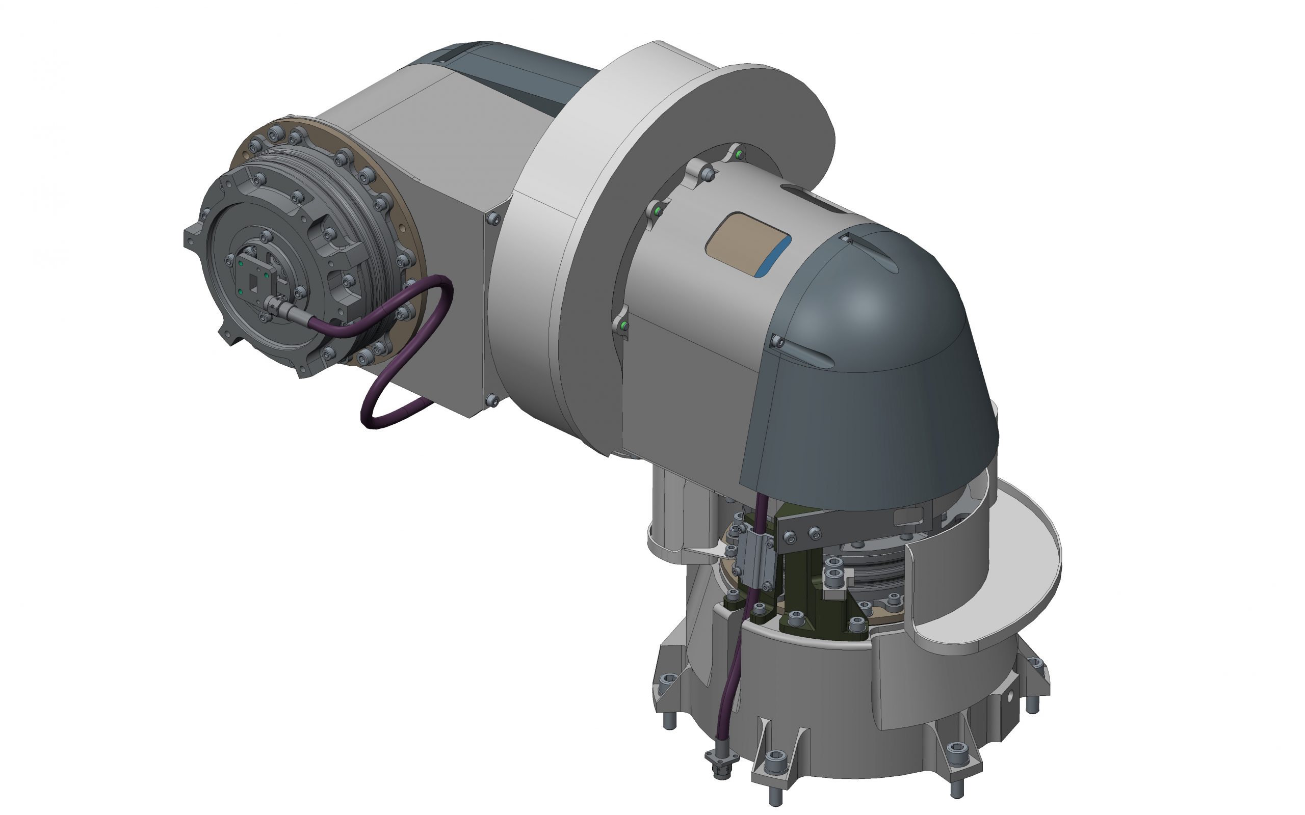
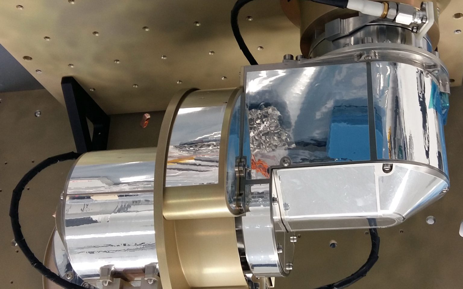
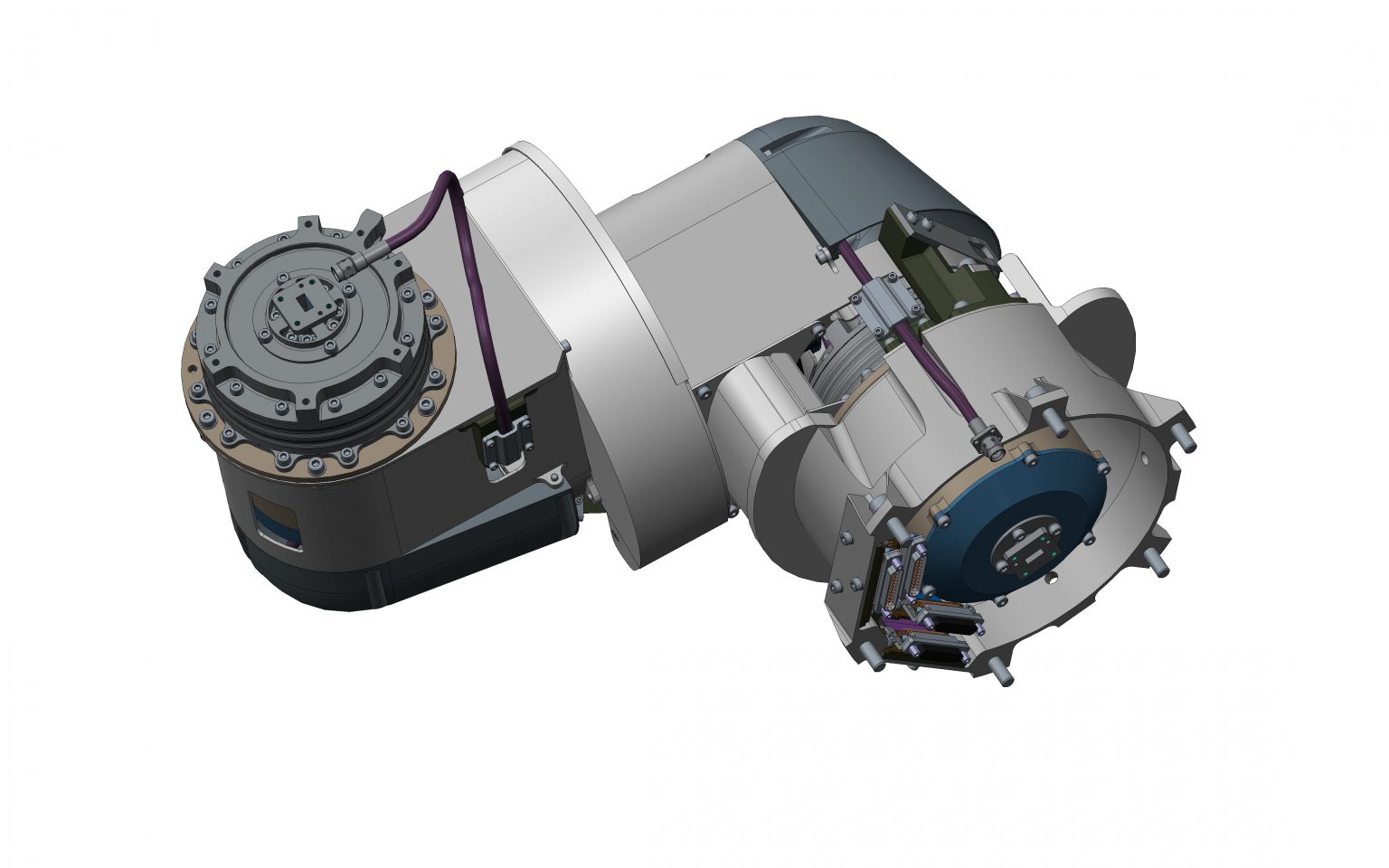
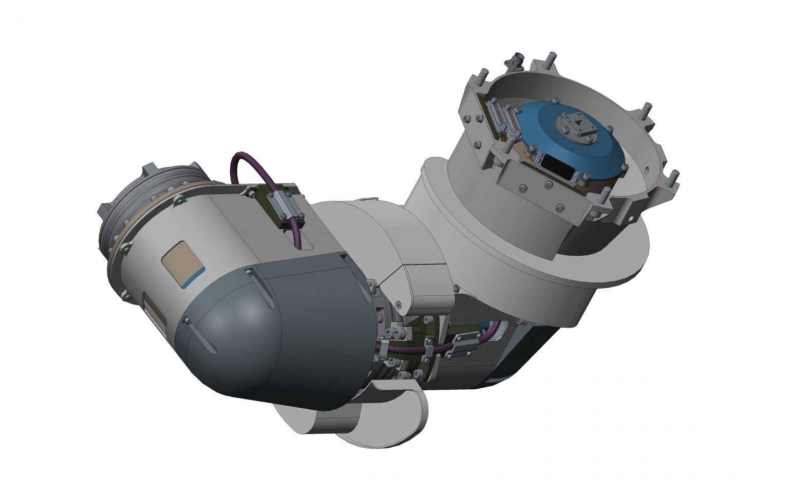
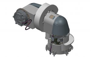
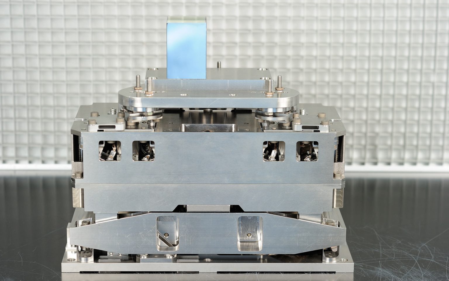
- Two Sunshield Bar-linkaje Mechanisms (SBM) with stepper motor actuator
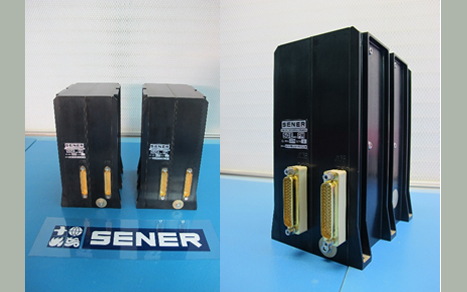
- Two Sunshield Drive Electronics (SDE) one for each actuator
- The two harnesses connecting the Sunshield Bar-linkaje Mechanisms and the Sunshield Drive Electronics
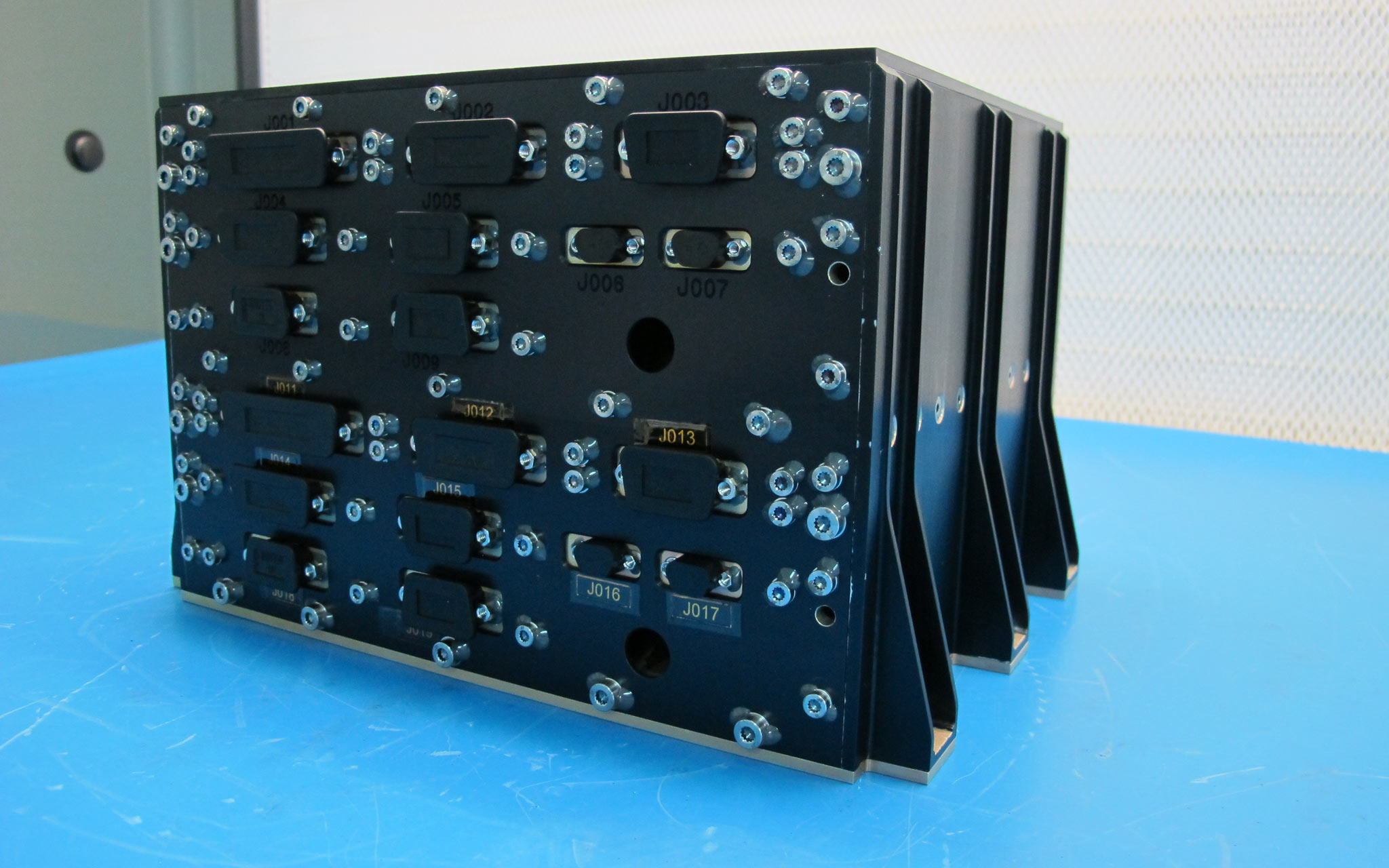
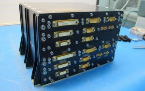
The SDE are formed by two electronic boxes that contains two electronic sections each one. These units are recurrent units from M2MM MDE of GAIA.
The SDE is an electrical unit designed to control a stepper motors per section (Main or Redundant) which shall actuate over the DSA Structure. The stepper motor mechanisms shall allow the DSA deployment.
Each SDE unit is housed in a single aluminum box, and it is internally divided in two fully similar sections, denoted as main and redundant, which are working in cold redundancy. The spacecraft is in charge of selection the nominal or redundant section. Every section is comprised of a hybridised DC/DC converter with integrated EMI filter, and one semi-rigid board. Each section shall command the motor using a current control loop. This scheme allows reducing the power deliver to the motor in the low temperatures where the motor resistance is lower.
A MIL-STD-1553 bus is used to manage the communication between the SDE units and the spacecraft. This link shall be used to send and receive all the telecommands and telemetries involving the motor commanding.
The Sunshield Drive Electronics (SDE) interfaces with the Power Control and Distribution Unit of GAIA satellite for the power and with the CDMU of GAIA satellite for the command control and housekeeping data. The SDE interfaces with nominal and redundant channels of mechanism actuators.
The main functions of the SDE are:
- DC/DC power conversion to provide secondary supplies to internal electronic part and to actuator drivers
- Acquisition of command to be applied to the actuators from 1553B bus of GAIA SVM
- House-keeping Monitoring and status transmission to 1553B bus of GAIA SVM
- Provision of power to drive the actuator
- Provision of excitation voltage to actuator potentiometers
The redundancy philosophy is a cold redundancy, i.e. Two electronic parts (main and redundant) drive one actuator on its nominal and redundant interfaces, however the activation of main and redundant parts will have a short overlap period. Both redundant and nominal electronics are kept within one SDE electronics box.
- cHARACTERISTICS:
- Mass: 2.2 kg.
- Size: 175 high, 130 long and 95 wide.
- Thermal: SDE unit is designer to have an operating range from 250K to 313K and non operating range of 230K to 313K. The MDE shall manage the M2MM that will have an operating range from 110K to 313K.
- Power:
– Power input bus: +28V
– Power Consumption: 15W (Duty cycle 100%); 12W (Duty cycle 75%); 9W (Duty cycle 50%)
– The max. dissipation by conduction for SDE < 8W
– The max. dissipation by radiation for SDE < 2W.
- Radiation environment: The unit is designed to tolerate a uniformly distributed total dose of 22 krad inside the box.
- Redundancy: Two fully redundant sections in a single box.
- Power conditioning: Every section has to be provided with an isolation converter with an integrated EMI filter
- Control: Every section is to be provided with an “intelligent” device capable of decoding all telecommands received via serial channels, providing the switching sequences required by the motors, and encoding the status information to provide serial telemetry.
- Motors drive: Up to ten independently biphased motors (with main and redundant wiring) can be managed by MDE main and redundant section in cold redundancy.