


SENTINEL-2. MSI Instrument Calibration & Shutter mechanism (CSM)
Sener developed the Calibration and Shutter Mechanism (CSM) for the Multi-Spectral Instrument (MSI) for the Sentinel-2.
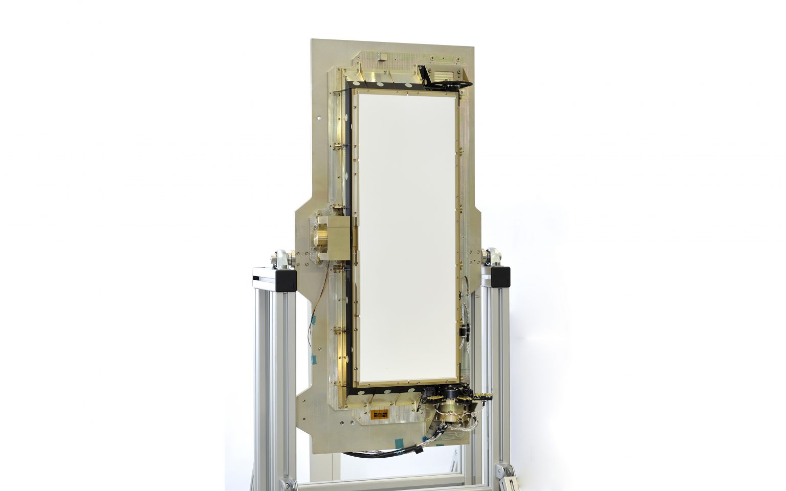
The Calibration and Shutter Mechanism (CSM) is located at the entrance to the optical instrument. During launch, it protects the instrument from sunlight and contamination, covering its entrance with a rectangular plate. This is the mechanism’s closed position, which must remain fixed under the action of the launch forces. Once in orbit, the mechanism performs the following functions:
- In order to permit observation mode,
Sener developed the Calibration and Shutter Mechanism (CSM) for the Multi-Spectral Instrument (MSI) for the Sentinel-2.
The Calibration and Shutter Mechanism (CSM) is located at the entrance to the optical instrument. During launch, it protects the instrument from sunlight and contamination, covering its entrance with a rectangular plate. This is the mechanism’s closed position, which must remain fixed under the action of the launch forces. Once in orbit, the mechanism performs the following functions:
- In order to permit observation mode, the plate rotates from the closed position 63° towards the inside of the instrument and keeps it in that position, without any power supply.
- Occasionally, in calibration mode, the mechanism inserts a solar diffuser in front of the primary mirror that receives direct sunlight. This position must also be maintained without any power supply.
- From any position, in the event of an emergency, the mechanism must rotate the plate to the closed position in order to prevent the sunlight from heating sensitive parts of the optical instrument.
In order to accomplish the aforementioned functions, the plate, which is a rectangular metal structure, is supported on one of the longest sides at both ends. At one end by means of an electromechanical rotary actuator, and at the other end by means of a ball bearing system. Both of them make up the plate’s axis of rotation.
At the opposite end, the plate is blocked during launch by means of an electromechanical component that inserts a pinpuller into a bushing installed on the plate. In orbit, the component releases the pin and the plate can rotate in both directions around the axis of rotation through the action of the electromechanical actuator.
The actuator comprises a stepper motor, a ball bearing system, and a harmonic gear that avoids play in the transmission of movement.
The control of rotation from one position to another is performed in an open cycle with a logic that cuts the power to the motor (halting the plate) when it receives a signal from a simple system of switches placed in each position and activated by magnets. The motor winding and switches are redundant.
- Characteristics:
- General dimensions: CSM: 1102 x 445 x 177 mm3 / Door: 815 x 320 x 47 mm3.
- Mass: CSM: 12.4 kg / Rotating mass: 5.6 kg.
- Launch configuration stiffness: 91 Hz.
- Step angle (resolution). 0.02°
- Step rate: 135 Hz
- Nominal angular range: 118º
- Actuator power consumption: 4.3 W
- LLD release power consumption: 27 Watts @ / 2.75 Amps < 300 ms
- Thermal range: -30°C ÷ +60°C
- Lifetime: 2460 opening/closing cycles.
- Quasi-static acceleration 50 g

