


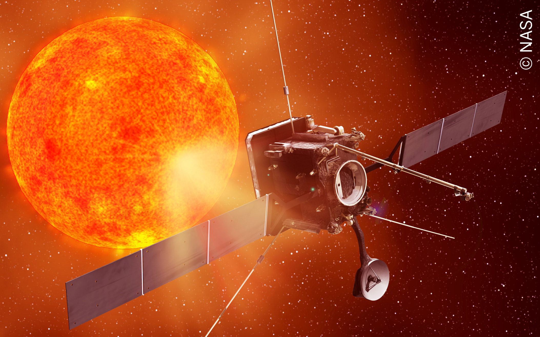
Solar Orbiter High Gain Antenna Subsystem (HGA S/S)


The main objective of the project was to design, manufacture, integrate, test and deliver the satellite’s complete antenna subsystem. This subsystem comprises four independent devices:
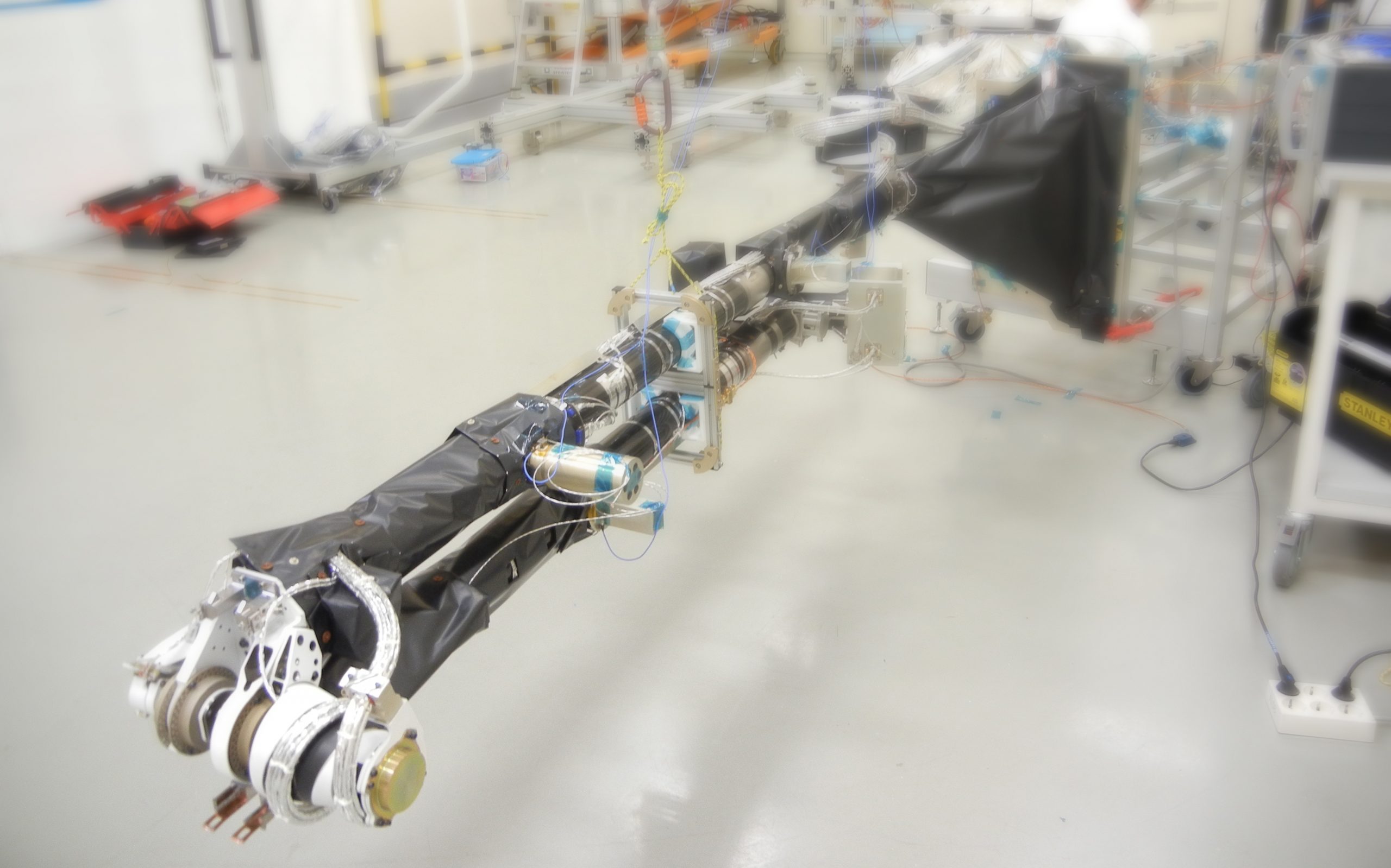
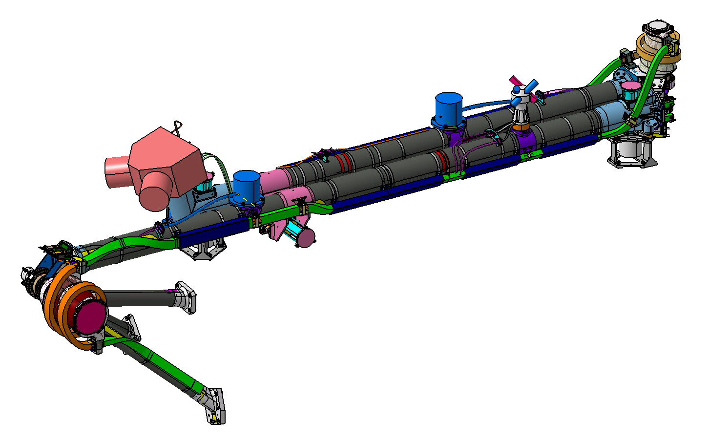
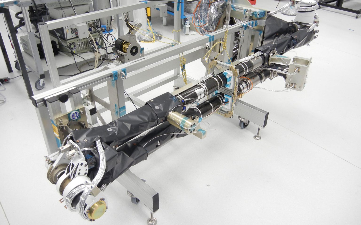
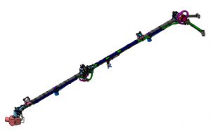
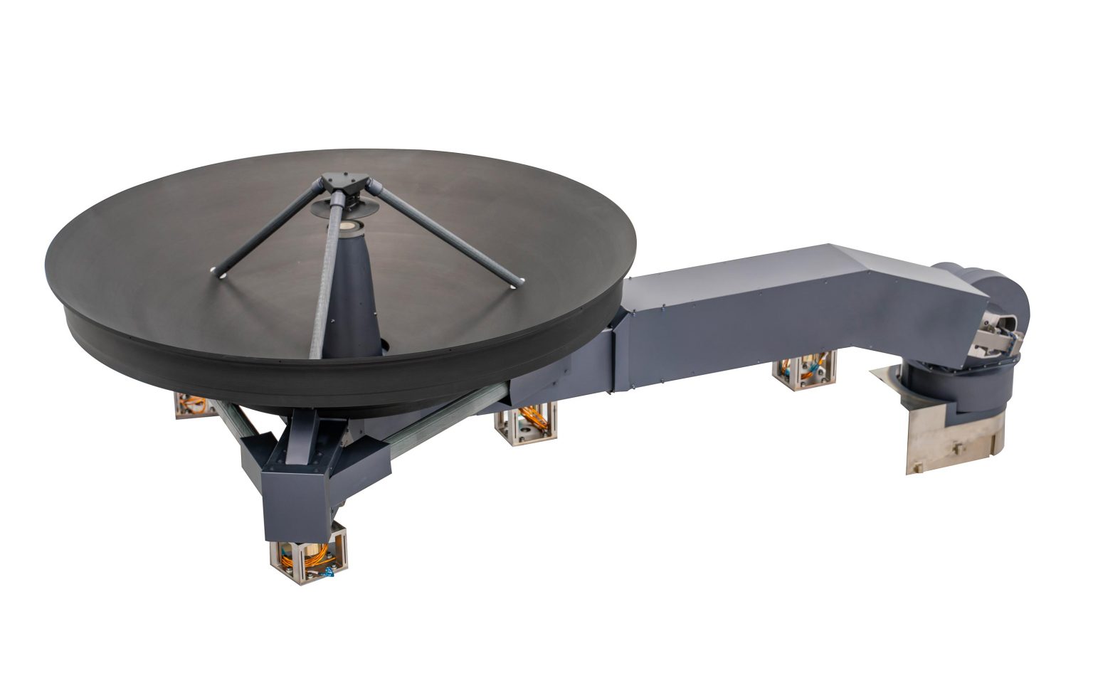
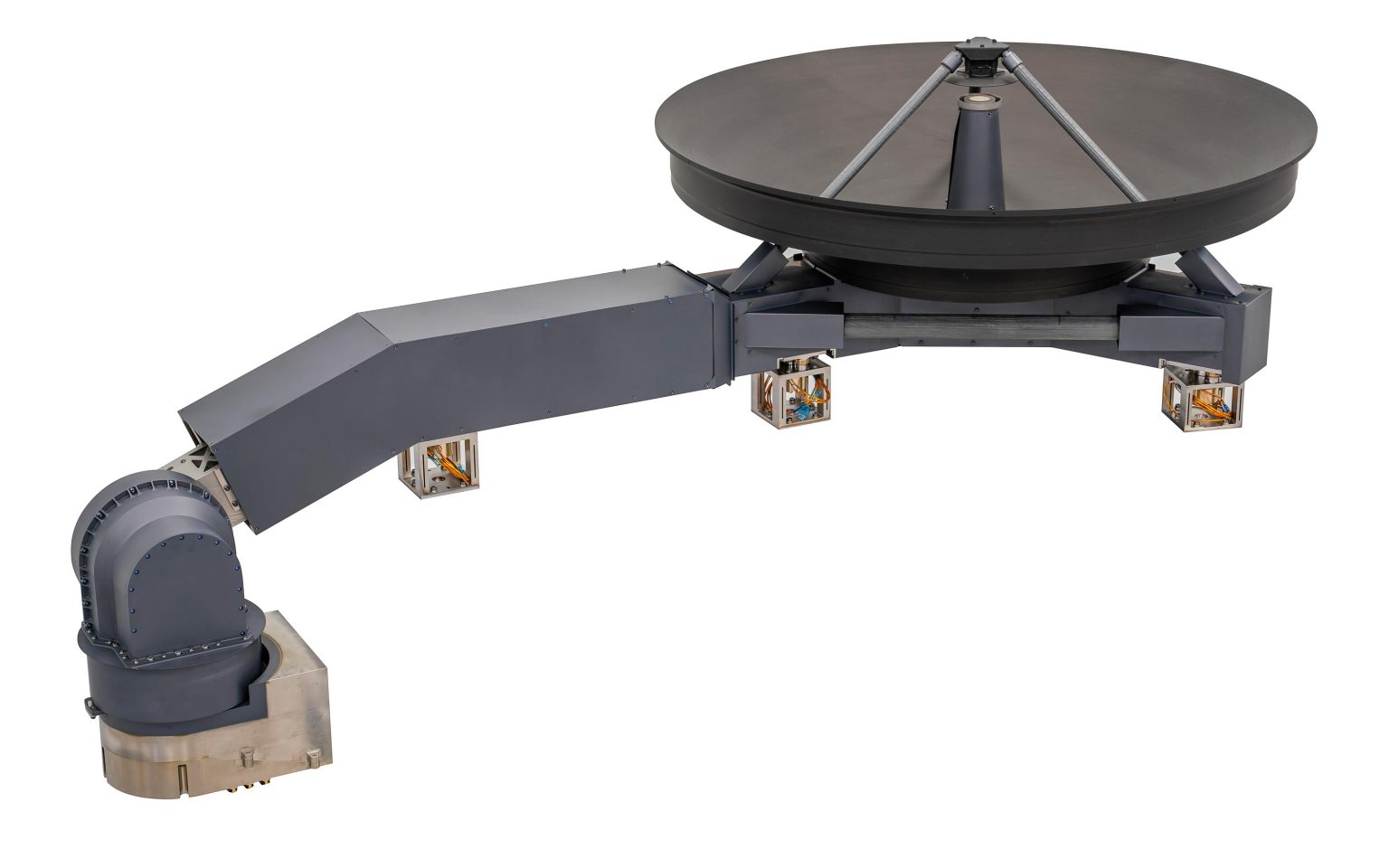
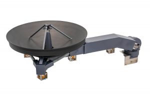
High Gain Antenna Major Assembly (HGAMA)
In turn, the HGAMA consists of:
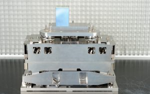
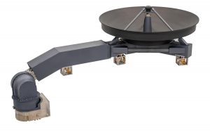
- An “axially displaced ellipse” reflector antenna made of titanium whose main reflector has a diameter of 1100 mm.
- A boom that permits antenna operation separately from the satellite.
- A two-axis antenna pointing mechanism (APM).
- Thermal shields and blankets to protect the entire assembly.
The main objective of the project was to design, manufacture, integrate, test and deliver the satellite’s complete antenna subsystem. This subsystem comprises four independent devices:
High Gain Antenna Major Assembly (HGAMA)
In turn, the HGAMA consists of:
- An “axially displaced ellipse” reflector antenna made of titanium whose main reflector has a diameter of 1100 mm.
- A boom that permits antenna operation separately from the satellite.
- A two-axis antenna pointing mechanism (APM).
- Thermal shields and blankets to protect the entire assembly.
- Four Hold-down and Release Mechanisms
- Antenna Pointing Mechanism Electronics (APME) located inside the satellite to control antenna pointing.
Medium Gain Antenna Major Assembly (MGAMA)
In turn, the MGAMA consists of:
- A horn antenna
- A 700-mm boom to articulate the antenna.
- Heat shield for the boom and thermal protection blankets of the APM.
- A Hold-down and Release Mechanism
- A single-axis Antenna Pointing Mechanism (APM) at the end of the boom.
- Antenna Pointing Mechanism Electronics (APME) located inside the satellite.
The MGAMA has certain similarities with the assembly of the same name being developed at Sener for the BepiColombo Mission.
Low Gain Antennas (LGAs)
Two Low Gain Antennas (LGAs) with semi-omnidirectional coverage, the combination of which allows the satellite to establish a communications link with the Earth in emergences or loss of attitude.
- Characteristics:
- The high gain antenna operates on the X band with gains of more than 36.5 dBi in downlink and more than 35.0 dBi in uplink.
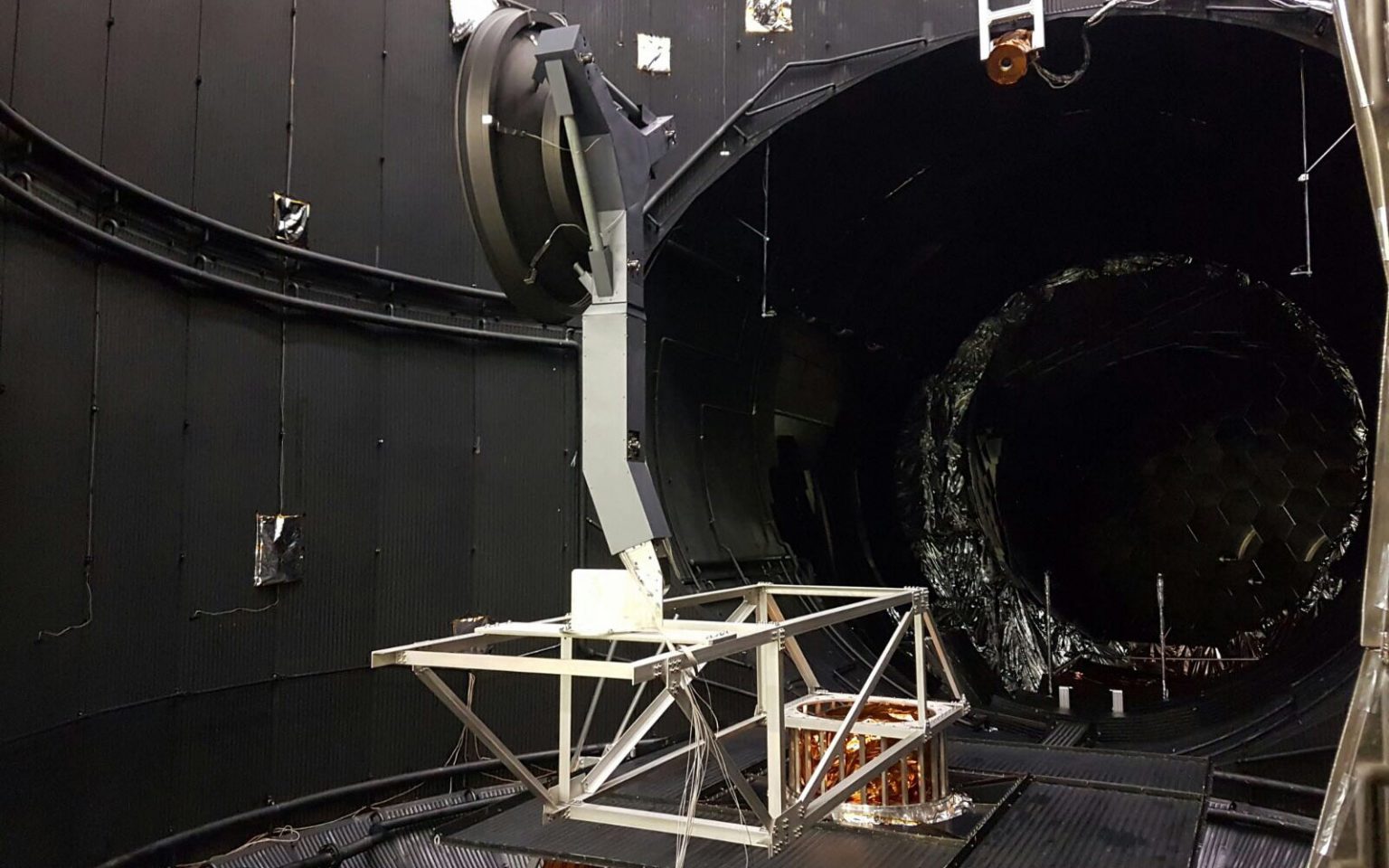
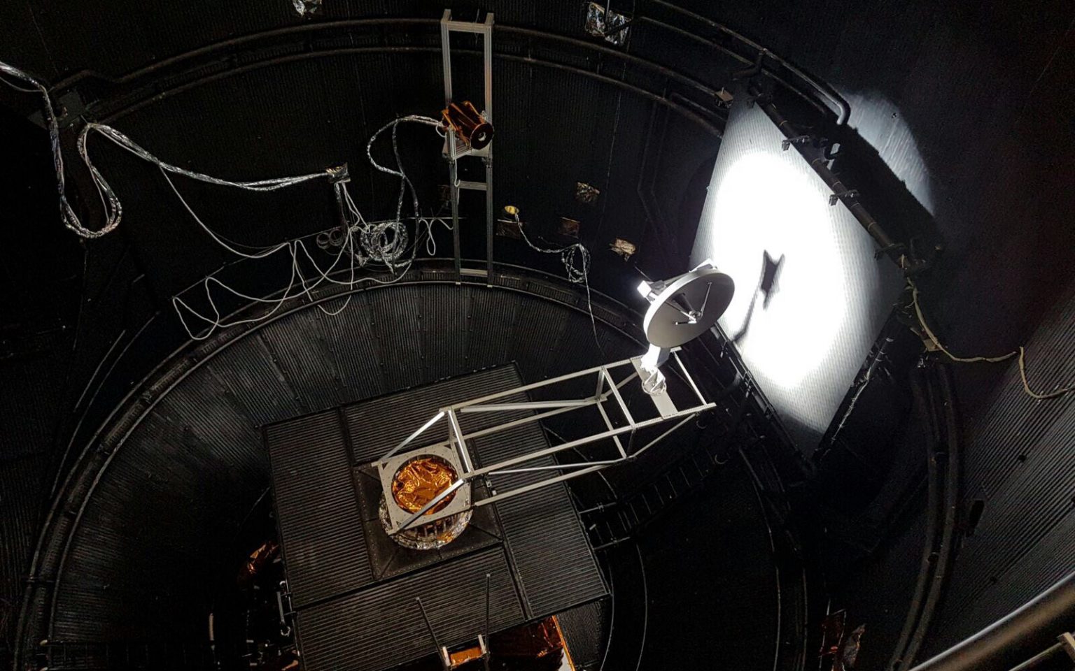
- The antenna operates at a power of 48.45 dBm in the required setting at less than 0.28 AU (astronomical units). The temperatures it must withstand during the science phase are 585ºC in areas exposed to the sun, and it has a special coating developed specially to guarantee that it will operate even in such a harsh environment.
- The unit operates on two axes at speeds of 0.5º/seconds with pointing stabilities compatible with the radio-frequency requirements.
- The medium gain antenna also operates on the X band with a gain of 22.3 dBi in downlink and 20.5 dBi in uplink with a power of 48.48 dBm. The antenna also operates during the science phase at the minimum distance from the sun, withstanding temperatures of 550ºC.
- The low gain antenna operates during the phase closest to Earth on the X band, transmitting the satellite’s telemetry data.
Related content
Contact us
Contact us to find out how we can help you.