


- Mobility & Infrastructures
Categories:
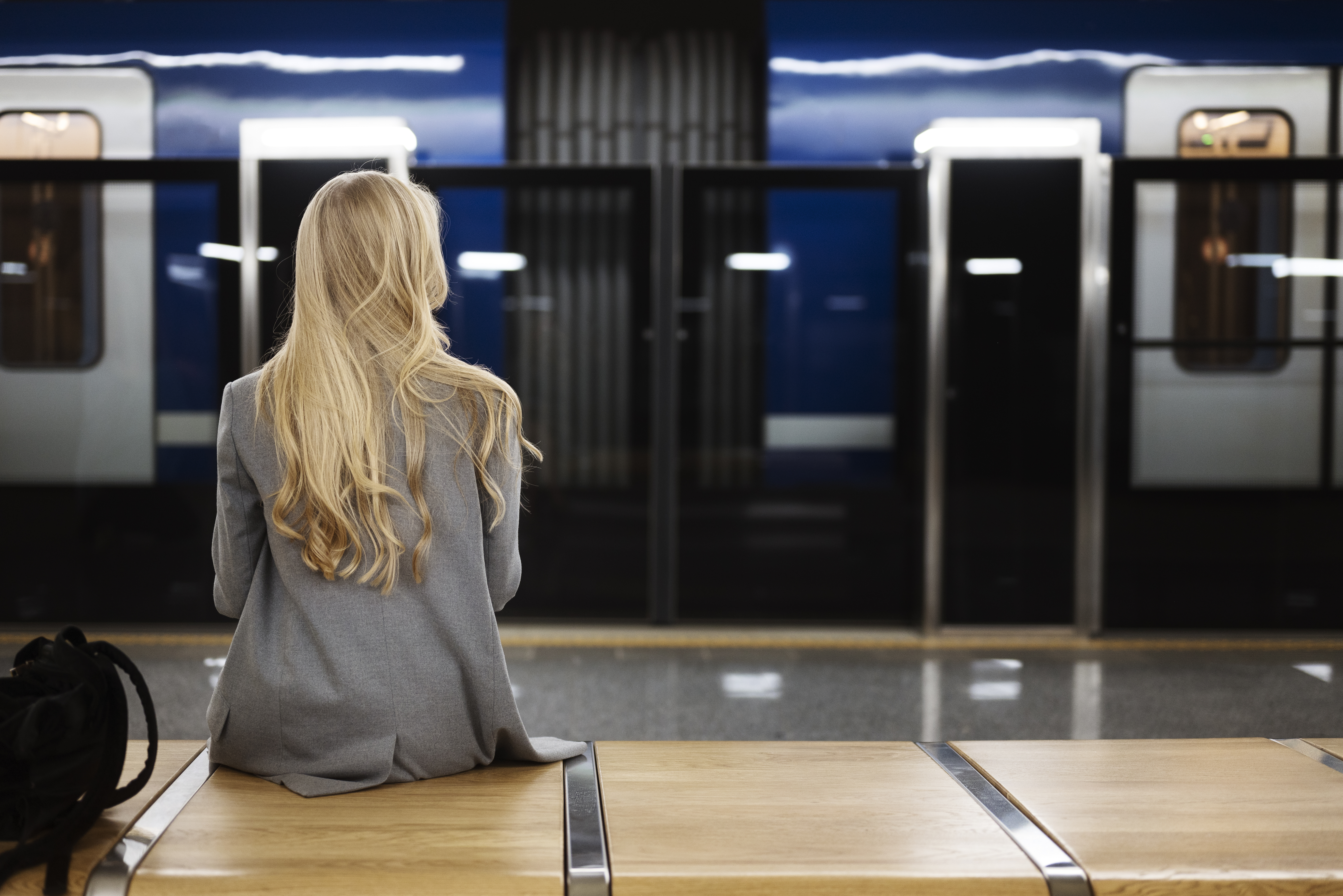
When passengers travel by metro, they rarely consider the complex network of systems that makes their journey safe and efficient. Behind every tunnel lies a sophisticated coordination of installations that must work in harmony.
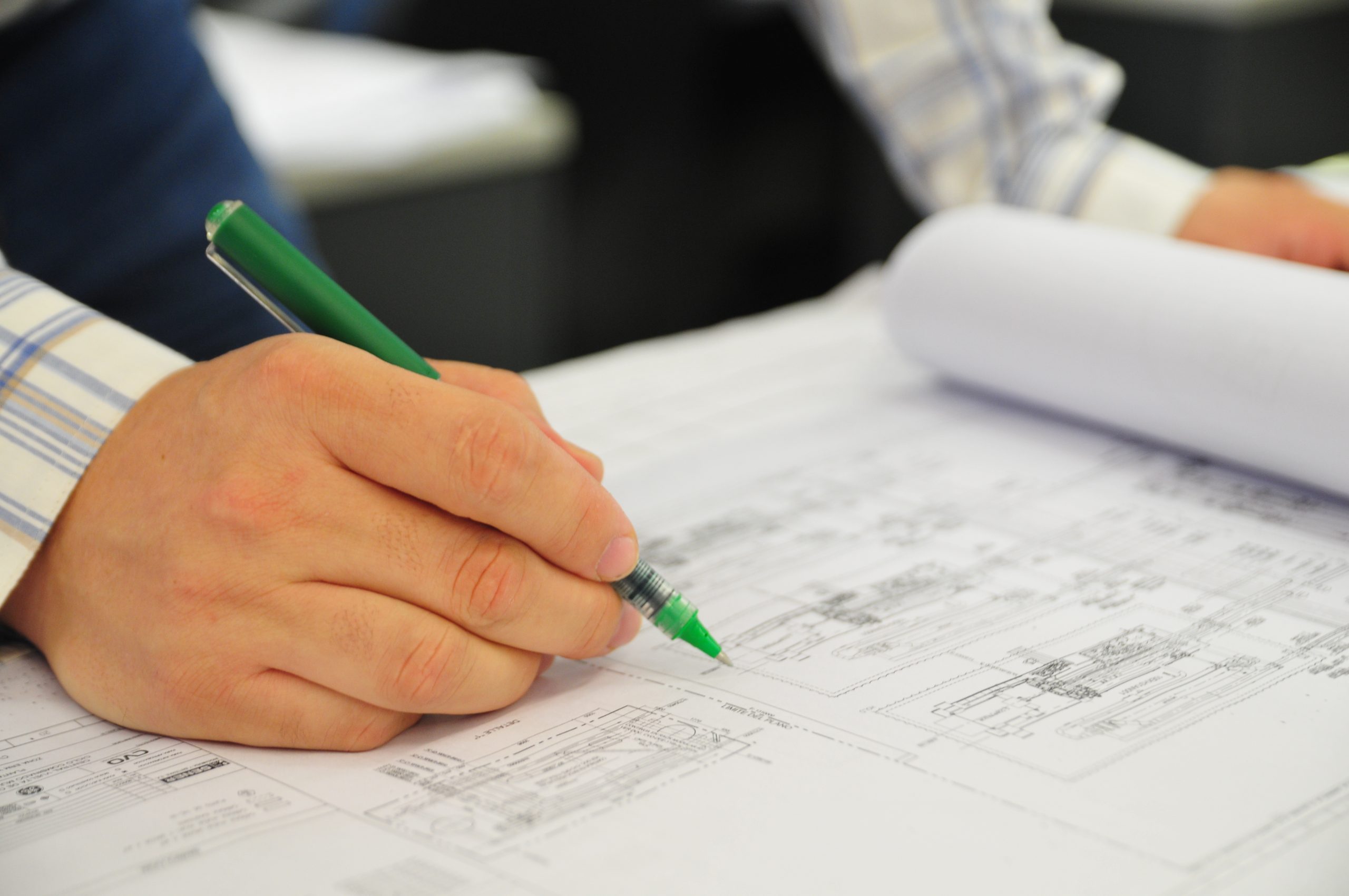
Coordinating these systems during the design phase poses a complex challenge in urban transport engineering. From the lighting that ensures safe evacuation to the signalling systems, every installation must find its place without interfering with the others.
This article outlines some of the installations to be coordinated and reviews several design principles applied during the project phase.
- Lighting in metro tunnels is provided by wall-mounted luminaires, ensuring adequate illumination both for emergency evacuation and for maintenance operations. The distance between luminaires must ensure appropriate and uniform illuminance levels. The wiring used is fire-resistant and protected against moisture and impact.
- Evacuation signage is essential to guide passengers towards the nearest exit in emergency situations. Signs may be static—using illuminated arrows or photoluminescent panels—or dynamic, adapting to different evacuation scenarios. In some cases, dynamic signage is required to manage the simultaneous evacuation of two trains within the same ventilation area.
- For maintenance operations, power sockets are installed along the tunnel to connect electrical tools. These sockets are impact-resistant and protected against earth leakage. Their wiring layout ensures that any unintended tripping of the protection systems leaves adjacent sockets operational.
- Track crossovers, strategically located before stations or at the end of lines, allow trains to access sidings or start new routes without reaching the end of the line. These mechanisms require electrical power from the nearest signalling room.
- In tight curves, track lubricators are installed which, through hydraulic pistons, apply lubricant to reduce wear on wheels and rails. These systems also require auxiliary electrical power.
- The third rail power supply is divided into several sections using automatic switches located in technical rooms. Additional isolators are installed within the tunnel to connect different power zones and ensure safety during maintenance operations by guaranteeing power disconnection. All these cabinets require auxiliary power with a backup system for proper operation and control.
- Emergency alarm stations are equipped with push buttons that allow the power to the third rail to be cut in the event of an evacuation. These are accompanied by emergency telephones and blue lights that identify their location in the tunnel. The cabling of these devices is fire-protected to ensure functionality in emergencies.
- Conventional signalling for running sections is carried out using light signals that indicate to drivers whether it is permitted to proceed. These signals are connected to electrical cabinets located along the maintenance walkway.
- Train detection is achieved using axle counters, which control light signals and emergency braking mechanisms. These mechanisms act on mechanical arms that, upon contact with a vehicle, trigger the required stop manoeuvre in case of non-compliance with safety conditions set by the signalling system.
- To indicate the presence of maintenance personnel on the track, light signals are installed at station exits.
- Communication cabling between stations uses primary and secondary fibre-optic networks, ensuring connectivity for both operational and emergency systems. Radiating cables are also installed for radio-frequency communications, essential for maintenance tasks and emergency situations.
- The firefighting water network extends from street level to the furthest points of the tunnel, supplying hose connections through a dry pipe system. Water collection, whether from infiltration or firefighting use, is managed through drainage channels that convey it to pumping stations located at the lowest points of the route.
Once the installations to be coordinated in the tunnel have been identified, coordination criteria are established.
An initial decision involves identifying which systems are necessary in emergency scenarios and defining the strategy for their fire protection—either by embedding conduits within the concrete of the walkways or by using fire-resistant cables installed on the tunnel walls.
The mechanical protection of cables installed on the surface—except for traction or signalling systems—considers impacts from small objects due to passing trains at high speed. Here, the choice lies between mounting cables inside conduits or, alternatively, using armoured cables.
Another key criterion concerns the minimum separation distances required to prevent interference between low-current and power cables, such as between the radiating cable for radio communications, telephone pairs and traction return cables.
Larger equipment, such as signalling cabinets or traction isolators, should be positioned on the side opposite the walkway used for passenger evacuation in case of emergency.
In conventional signalling systems, where signals are placed on the driver’s side of the train, the evacuation walkway should ideally be on the opposite side to minimise obstacles along the evacuation route.
A symphony of disciplines and systems to ensure project success
The successful coordination of installations in metro tunnels goes beyond technical aspects: it is an exercise in multidisciplinary integration. The outcome depends largely on the project team’s ability to gather, analyse and implement the specific criteria of each discipline involved.
This coordination is not only a technical necessity but also a challenge that demands a global vision, meticulous attention to detail and a deep understanding of how each individual system contributes to the operation.
Ultimately, the success of a metro tunnel project is measured not only by its technical performance, but by its ability to deliver safe, efficient and reliable transport to millions of urban users.
The coordination of installations therefore represents one of the most demanding and rewarding aspects of transport engineering, where every technical decision has a direct impact on the daily lives of cities and their inhabitants.
- subway
Tags:
Author
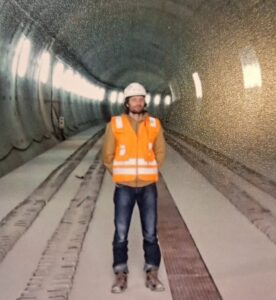
Xavier Taulè
Xavier is part of the transport infrastructure team in the Spanish section of Sener’s MEP Discipline. With 25 years of experience in the design of electrical and mechanical installations in the infrastructure and building sectors, he joined Sener in September 2023. In the railway sector, he has taken part in the testing phase of fixed installations at the stations of Line 9 Section 1 of the Barcelona Metro, in the development of the detailed design for the stations, depot, workshop and tunnel of Line 5 of the Riyadh Metro, and he is currently part of the team responsible for the detailed design of the electrical installations for the extension of the Line 2 tunnel in Toronto.

